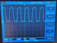
Lets try...I see a pattern... around 4 square wave is 7 divisions. So 7÷4= 1,75 division each square. Then... by division it results a wave has period of 175ns.
Frequency = 1/ 175ns = 5,71MHz
Too low, going to measure again, now 1x probe

4 waves are 7 divisions
Same as before 1,75 div./ wave = 175 nSec = 5,71MHz.
I am playing music trough the dac, still one channel dead, but the healty one sound is way better than yesterday, looks like the signal is stronger by the Firdac addition and while not perceived any gain, it keep turn up the volume without distortion. Eager to fix the stereo...
Frequency = 1/ 175ns = 5,71MHz
Too low, going to measure again, now 1x probe

4 waves are 7 divisions
Same as before 1,75 div./ wave = 175 nSec = 5,71MHz.
I am playing music trough the dac, still one channel dead, but the healty one sound is way better than yesterday, looks like the signal is stronger by the Firdac addition and while not perceived any gain, it keep turn up the volume without distortion. Eager to fix the stereo...
Last edited:
OK, so for reasons that aren't clear, your PCM2DSD produces a DSD128 rather than a DSD256 signal. Do you use xx3stksm's configuration file perhaps? I know PJotr25's versions should produce DSD256 and mine DSD512, I don't remember what rate xx3stksm used.
In any case, from your experience with the low-pass filter and the various oscilloscope plots, it is clear that there is nothing wrong with this DSD128 signal.
The DAC produces a good-looking doubled clock. The return-to-zero logic processes one signal for the channel that doesn't work correctly, the other comes out like a non-return-to-zero signal.
I would expect the channel that doesn't work correctly to at least produce some sound, despite the problem with the return-to-zero logic. It doesn't, though.
Do you see any lose connections of the 74LV574s?
If the pin of R132 that goes to the 74LV574A's is not making contact with the PCB trace, you would have a single fault that can make the left channel silent, and you would not see that anything is wrong when you probe at the resistor. Maybe it's a good idea to do a continuity test from R132 to the clock inputs of the left channel 74LV574A's, simply with a multimeter with everything switched off.
Sorry delay Marcel, yes yes it has been a 74LV574A short. But I have delayed the answer till now having fixed the stereo. But before was still remaining faulty. I have reflow all IC smd but using good quality solder wire. Now all solder points are much more shiny than before, I regret having used low temp solder paste + stencil. Puag, never more! After good cleaning (to the madness) the unit work wonderful in stereo as expected.
I leave here very grateful, I could not have asked for more, thanks many thanks everybody here this is amazing community.
Jordi
I leave here very grateful, I could not have asked for more, thanks many thanks everybody here this is amazing community.
Jordi
Last edited:
Last edited:
What does CRFB stand for, what does it have to do with this thread and why the bold letters?
If it relates to my alternative configuration files for PCM2DSD: I've tried to minimize noise modulation, so it by design produces about the same noise at 0 input signal as with any other input signal.
If it relates to my alternative configuration files for PCM2DSD: I've tried to minimize noise modulation, so it by design produces about the same noise at 0 input signal as with any other input signal.
Anyway, the sigma-delta modulator of post #4043, https://www.diyaudio.com/community/threads/return-to-zero-shift-register-firdac.379406/post-7895559 , and its earlier versions by default have all their requantizers (rounding stages) dithered to make the average and standard deviation of the rounding error independent of the signal. Because of ergodicity, that also means their noise power is independent of the signal, so it stays the same when the input signal to the modulator is 0. There is still some remaining noise modulation because I found no way to make the standard deviation of the error of the embedded pulse width modulator signal-independent.
More generally, sigma-delta modulators are usually designed to be either at or just over the edge of chaos, so even without dither, their limit cycles are unstable. When you start them with initial conditions that don't exactly fit with a limit cycle or when you apply any disturbance at all, you will get a noise-like output signal.
More generally, sigma-delta modulators are usually designed to be either at or just over the edge of chaos, so even without dither, their limit cycles are unstable. When you start them with initial conditions that don't exactly fit with a limit cycle or when you apply any disturbance at all, you will get a noise-like output signal.
Last edited:
@MarcelvdG My 7th-order CRFB Delta-sigma modultor with 256 OSR output appears "Noise-like" ,even with a zero input,when the inital input is zero,the outpu is silent,then the input begin to zero or DC,the modultor output appears "Noise-like",this problem bother me a long time ,I no idea to solve it
If you wanted it to be always noise-like, you could try nonzero initial conditions or add some dither. I don't know any straightforward way to make it produce repetitive patterns during silence, other than detecting a series of zero input samples and using a multiplexer to switch between the sigma-delta modulate and a repetitive pattern. You could try shifting all the loop filter poles just inside the unit circle, but chances are that that much degrades noise shaping and idle tone behaviour.
You could add some local negative feedback around each integrator to make them "leaky" and thereby shift all loop filter poles just inside the unit circle, hoping to make the limit cycles stable by doing that. Chances are that this causes worse problems than it solves, but you don't know for sure until you try.
when I reduce the first integrator feedback of the resonator ,the noise-like output diminished and the idle-tone grow upYou could add some local negative feedback around each integrator to make them "leaky" and thereby shift all loop filter poles just inside the unit circle, hoping to make the limit cycles stable by doing that. Chances are that this causes worse problems than it solves, but you don't know for sure until you try.
Last edited:
Yesterday I made a big improvement. I discovered that I could use the potential of the DAC with its balanced architecture, coupling it to the balanced option that was also available on the Stepup transformer (6.5X).
The sound turned out to be more saturated, much better in every way. Unfortunately balanced only allows me to listen in mono (I mean one channel).
I had to revert to single ended stereo, until I received the components, I have already ordered the inductors to build another "stereo" filter, necessary for the second "balanced" channel.
Till now I have been used a 4rt order butterworth low pass filter at 30kHz.

In the process to complete the second pair for the balanced signal, I discovered by chance, how much footprint the quality of components give to the final sound.
So I flirted with the idea to try a higher cutout frequency filter, since with less capacitance and inductance the components hurt less the audio signal.
Also, a 3rd Order reduces number of inductors to one per channel.
To do so I played around the simulator.
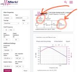
https://markimicrowave.com/technical-resources/tools/lc-filter-design-tool/
After a while I strumbled in a 32kHz 3rd order. Very convenient in my case.

The typed red arrows are impedance values in ohm, those parts are not resistors.
The left arrow signaling 50 ohm, is RTZ Firdac output impedance (I found by empirical listening tests), on the right arrow it is mandatory the same inductance - not to damage the already weak signal- (50R load equals the stepup 6,5x properly tuned with 2Kohm load).
True filter values ( CLC) are = 100nF + 500uH + 100nF. In my case are very convenient, looks like a simplified version of my existing 200uH + 220uF + 500uH + 100uF.
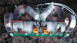
What a chance, to know if this setting has better sound, I only need to remove my existing first inductor and change the input capacitor. I will listen empiricaly the sound diference! Estrategically I have placed four switches temporarily to allow not only listen but compare 'on the fly'.
See pic atch., four scwitches placed and on top, the 0,1uF contenders.

This dac is very revealing and musical, a joy to play with. It took me not long to notice that a veil was lifted in sound of the simplified filter. And no drawbacks, that's why I share here with confidence. By my humble opinion and despite the weakness of signal here, the parts deserved to be higher quality as possible, audiophile components like those often used on loudspeaker crossovers (flat copper air core inductor + best caps can afford, correctly orientated the outerfoil, etc..).
I am tempted to go even further, a 40kHz cutoff gives even milder values 82nF+ 390uH+ 82nF.
Till how much higher the frequency cutoff can still clean the RTZ Firdac DSD noise?

In the process to complete the second pair for the balanced signal, I discovered by chance, how much footprint the quality of components give to the final sound.
So I flirted with the idea to try a higher cutout frequency filter, since with less capacitance and inductance the components hurt less the audio signal.
Also, a 3rd Order reduces number of inductors to one per channel.
To do so I played around the simulator.
https://markimicrowave.com/technical-resources/tools/lc-filter-design-tool/
After a while I strumbled in a 32kHz 3rd order. Very convenient in my case.

The typed red arrows are impedance values in ohm, those parts are not resistors.
The left arrow signaling 50 ohm, is RTZ Firdac output impedance (I found by empirical listening tests), on the right arrow it is mandatory the same inductance - not to damage the already weak signal- (50R load equals the stepup 6,5x properly tuned with 2Kohm load).
True filter values ( CLC) are = 100nF + 500uH + 100nF. In my case are very convenient, looks like a simplified version of my existing 200uH + 220uF + 500uH + 100uF.
What a chance, to know if this setting has better sound, I only need to remove my existing first inductor and change the input capacitor. I will listen empiricaly the sound diference! Estrategically I have placed four switches temporarily to allow not only listen but compare 'on the fly'.
See pic atch., four scwitches placed and on top, the 0,1uF contenders.

This dac is very revealing and musical, a joy to play with. It took me not long to notice that a veil was lifted in sound of the simplified filter. And no drawbacks, that's why I share here with confidence. By my humble opinion and despite the weakness of signal here, the parts deserved to be higher quality as possible, audiophile components like those often used on loudspeaker crossovers (flat copper air core inductor + best caps can afford, correctly orientated the outerfoil, etc..).
I am tempted to go even further, a 40kHz cutoff gives even milder values 82nF+ 390uH+ 82nF.
Till how much higher the frequency cutoff can still clean the RTZ Firdac DSD noise?
Last edited:
- Home
- Source & Line
- Digital Line Level
- Return-to-zero shift register FIRDAC