In order to impress anyone here I think it needs to look like:

and no oven will fix that...
//
and no oven will fix that...
//
@savan I'm just one person but maybe your general questions, observations etc could be posted to a fresh thread, so that this one stays on topic? Just a suggestion. I'm (very) interested in how the primary contributors to the development and enhancement of this design are doing...

I implemented each FIRDAC using 16 single gate flip-flops. Any equivalent of LVC1G74 will do well.
Each flip-flop has individual decoupling cap 1uF 0603 and distributed electrolithic caps totally about 800uF.
Reference was built on 6 directly biased P-N junctions of BJT transistors and buffered with very low noise OPAMP. Thermal stability was sacrificed for the sake of Vnoise. It shows about a quarter of micro volt rms in 20-20k.
Do you use separate flip-flops for the positive and negative sides of a differential FIRDAC or are they combined, using both Q and QN?
Not at all. The strange harmonics reported in #3865 are not related to "idle tones" at all.Both, as far as I'm concerned.
This is an effect of shitty DSD principle of using 1-bit SDM for data representation.
The 1-bit data is of the constant power. Signal + Noise = 1 all the time.
At 0dBV level we have 50% of the signal power going into sine, but 50% - into quantization noise.
At -60dBV only 0.0001% is sine and 99.9999% is high frequency noise, that you have to remove by reconstruction LPF.
On the other side PWM+FIRDAC shows much better performance, because of PWM noise spectrum is tightly clustered around carrier sub-harmonics. Fortunately, FIRDAC removes this kind of noise very effectively. I can't say the same about DSD.
It is an intermodulation products created at the input stage of the OPAMP by high level of quantization noise, essentially when signal as low as -60dB.
If you still insist in existence of the "idle tones", I can present a simulated spectrum of the modulator for -60dB 1kHz tone.
There is nothing there even at -190dB! The model is exact, including fixed point arithmetic and truncation errors.
Last edited:
Combined.Do you use separate flip-flops for the positive and negative sides of a differential FIRDAC or are they combined, using both Q and QN?
@ska : Hi ... very interesting to follow your inputs here ... & impressive results!
One question in relation to these couple of sentences of yours:
Does this mean that the output filtering from your PWM based DAC needs less (i.e. potentially simpler) analog filtering to achieve a similar level of output noise attenuation?
Cheers, Jesper
One question in relation to these couple of sentences of yours:
On the other side PWM+FIRDAC shows much better performance, because of PWM noise spectrum is tightly clustered around carrier sub-harmonics. Fortunately, FIRDAC removes this kind of noise very effectively. I can't say the same about DSD.
Does this mean that the output filtering from your PWM based DAC needs less (i.e. potentially simpler) analog filtering to achieve a similar level of output noise attenuation?
Cheers, Jesper
It is an intermodulation products created at the input stage of the OPAMP by high level of quantization noise, essentially when signal as low as -60dB.
Of course it's an intermodulation product. That's what I have been writing all the time. Whether it is created by an op-amp is unknown; it might as well be created by other analogue imperfections, such as data-to-clock crosstalk, data-to-reference crosstalk or some intersymbol interference due to imperfect settling.
When the signal is just a small offset, the intermodulation product is a tone or a narrow noise bump. That's why it is commonly known as an idle tone.
Example of intersymbol interference:
Fifth-order single-bit sigma-delta modulator of post #2696, no dither, small offset as input signal.
Horizontal scale in Hz, vertical in dB DSD, Hann window, bin size 100 Hz
Red trace: ideal case
Green trace: some second-order intermodulation introduced by making the bit weight vary +/- 1 ppm depending on the previous bit
If you still insist in existence of the "idle tones", I can present a simulated spectrum of the modulator for -60dB 1kHz tone.
There is nothing there even at -190dB! The model is exact, including fixed point arithmetic and truncation errors.
Why are you so focussed on everything digital? Are you a digital designer?
Anyway, would you kindly look at what the spectrum looks like around fs/2 and how that changes with a little offset? Do keep in mind that there is an image on the other side of fs/2, and then think about what happens with a little second-order intermodulation somewhere.
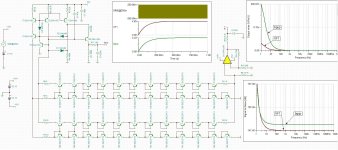
Remember, that total output power is constant = signal+error.Does this mean that the output filtering from your PWM based DAC needs less (i.e. potentially simpler) analog filtering to achieve a similar level of output noise attenuation?
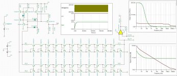
PWM spectrum is more peaky, concentrating a lot of noise energy in a small resricted areas, almost exactly at the position of zeros of the simple comb filter (FIRDAC).
First frame is PWM, second - PWM+FIRDAC.
Last edited:
@ska : Thanks for your feedback & the .gif ... A quite intuitive illustration - thanks 😉
Just from looking at the difference between the pure PWM modulation and the PWM+FIRDAC it seems as if this combination has some merit in attenuating higher frequency noise although I reckon some analog filtering is still necessary.
And then I am a bit surprised that since there are these very focussed noise "streaks" from the PWM modulation (> 1 MHz) that you in your #3863 measurement are able to produce an FFT with no "noise pins" whatsoever. Impressive work ...
Cheers & thanks again,
Jesper
Hi All.
I finally got filterboards, two different, for the RTZ dac.
I know my build will not win any beauty contest, but it is a bit like a prototype. A lot of things shall be tried before the final version.
The power supply for the dac is from another project, modified to fit the bill here. The batteries are LifePo4 and they power the filterboards. The small pototype print on top of the filterboard, is a relay that couples the batteries in when playing. The batteries are charged, when not playing and the 230 V to the charging PS is disabled while playing.
Bravo Marcell! It surprised me , just how good this is compared to the other No-dac versions I have made , including DCS 2.5 in the latest iteration.


I tried both the filter with OPA2210-1678 and the one with OPA1632.
It was a little difficult to compare the two as the OPA1632 board has more gain than the OPA2210-1632.
2210-1678 delivers around 1,9 V RMS @ 0 dB 1 kHz.
1632 delivers around around 3.73 V RMS @ 0dB 1 kHz.
I haven't looked into the reason why.
I preferer the 2210-1678 to the 1632.
1632 is a bit softer and has less separation between instruments and not quite as deep and precise a soundstage as 2210-1678.
These are first impressions after listening to them yesterday.


The reason for the different in sound could be , that the 2210-1678 circuit acts better as a virtual ground , than the 1632 as can bee seen in the scop dumps of the input to the filterboards. First 2210-1678 next 1632:


I finally got filterboards, two different, for the RTZ dac.
I know my build will not win any beauty contest, but it is a bit like a prototype. A lot of things shall be tried before the final version.
The power supply for the dac is from another project, modified to fit the bill here. The batteries are LifePo4 and they power the filterboards. The small pototype print on top of the filterboard, is a relay that couples the batteries in when playing. The batteries are charged, when not playing and the 230 V to the charging PS is disabled while playing.
Bravo Marcell! It surprised me , just how good this is compared to the other No-dac versions I have made , including DCS 2.5 in the latest iteration.
I tried both the filter with OPA2210-1678 and the one with OPA1632.
It was a little difficult to compare the two as the OPA1632 board has more gain than the OPA2210-1632.
2210-1678 delivers around 1,9 V RMS @ 0 dB 1 kHz.
1632 delivers around around 3.73 V RMS @ 0dB 1 kHz.
I haven't looked into the reason why.
I preferer the 2210-1678 to the 1632.
1632 is a bit softer and has less separation between instruments and not quite as deep and precise a soundstage as 2210-1678.
These are first impressions after listening to them yesterday.
The reason for the different in sound could be , that the 2210-1678 circuit acts better as a virtual ground , than the 1632 as can bee seen in the scop dumps of the input to the filterboards. First 2210-1678 next 1632:
Is this ok to add some bgup and VF1 RC for noise surpress or you prefering faster startup without those capacitors? I do not see capacitors on your schematic? Also I have changed some resistor values for getting 5V and 3.3V, is it ok? Bgup is noisy even when I put RC network,
Edit: picture 2 without RC, nice startup but SNR is significantly worse. Whats prefered, with or without RC? Thanks
Edit: picture 2 without RC, nice startup but SNR is significantly worse. Whats prefered, with or without RC? Thanks
Attachments
Last edited:
bgup is used to indicate to the muting circuit that the bandgap has started up, there is no reason why it should be low noise.
When you use different transistors than I use, you need different resistor values.
When you use different transistors than I use, you need different resistor values.
I'd suggest just building Marcels dac and listening to it , it really is excellent and you can experiment with different input stages and output filter stages .
I didn't hear any difference, neither in a sighted nor in a blind test, but that doesn't mean much, as I expected not to hear any difference.
Marcel, may I ask if you did all the other stuff first such as using external clocking, and then reclocking just before the dac?
If not, I think it can be hard to compare since the dac performance is not nearly as good without taking care of some of the worse problems first.
What I suggested to a few people using an OPA1632 output stage was to ground the inverting input of the output stage to dac ground through a 470R resistor (to roughly approximate the dac's inverting output impedance). After the OPA1632 output stage DC blocking caps may needed.
No.
I know, one of them asked my advice. I would suggest using a resistor that is a bit closer to 378.75 ohm. The nearest E12 value is 390 ohm, the nearest E96 value 383 ohm.
The unused DAC output can then be terminated to ground with either a 200 ohm resistor or the upper circuit of this sketch, with all values rounded to something practical:

This is assuming the OPA1632 filter is filter is filter 3 from post #2471. (There were several filters with OPA1632s mentioned in this thread.)
I know, one of them asked my advice. I would suggest using a resistor that is a bit closer to 378.75 ohm. The nearest E12 value is 390 ohm, the nearest E96 value 383 ohm.
The unused DAC output can then be terminated to ground with either a 200 ohm resistor or the upper circuit of this sketch, with all values rounded to something practical:
This is assuming the OPA1632 filter is filter is filter 3 from post #2471. (There were several filters with OPA1632s mentioned in this thread.)
Last edited:
Yes, understood. IIRC, I did try loading the dac inverting output to match what my transformer input roughly looks like. I didn't like the sound better that way, so I decided to leave the inverting output unloaded. I know, of course, it goes against theory. But I still ended up leaving it unloaded. So, I would be interested to see what other folks think if they try loading it or not.
- Home
- Source & Line
- Digital Line Level
- Return-to-zero shift register FIRDAC