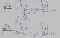
Isn't the part closest to the XLR connectors in https://www.diyaudio.com/community/attachments/rtz1-jpg.1199168/ a reconstruction filter?
Yes, my board has the same filter as original without the last stage. I.e. it has the filter deemed to sound best a while ago.
Same as this: https://www.diyaudio.com/community/threads/return-to-zero-shift-register-firdac.379406/post-7365893
Although I modified the gain of the filter to provide about 4 Vrms at 0dBFS as that is what I use with my other dacs and also the ADC input is tuned to that.
Same as this: https://www.diyaudio.com/community/threads/return-to-zero-shift-register-firdac.379406/post-7365893
Although I modified the gain of the filter to provide about 4 Vrms at 0dBFS as that is what I use with my other dacs and also the ADC input is tuned to that.
Last edited:
Regarding clock phase noise dividing MCK by 8 would theoretically lower the phase noise by 18dB. So NZ2520SDA gets closer to SOTA clocks. For this same reason DCLK reclocking is in theory an inferior solution.
I disagree with that. Dividing by eight with a not very clean divider and then reclocking with the original clock using a flip-flop with a clean supply is simply one way of making a clean divider by eight.
The reason why close-in phase noise ideally improves by 18 dB when you divide by eight, is that the time jitter stays the same, but the period time gets 8 times as large. The phase fluctuations are therefore 8 times smaller. For the phase noise floor, aliasing effects reduce the improvement to 9 dB.
The reason why close-in phase noise ideally improves by 18 dB when you divide by eight, is that the time jitter stays the same, but the period time gets 8 times as large. The phase fluctuations are therefore 8 times smaller. For the phase noise floor, aliasing effects reduce the improvement to 9 dB.

Ok. I need the test DCLK reclocking as well.I disagree with that. Dividing by eight with a not very clean divider and then reclocking with the original clock using a flip-flop with a clean supply is simply one way of making a clean divider by eight.
I based my comment on this.I have a question: Why does removing the stage sound better?
I left the final stage out because those film caps take too much space and all my downstream devices can handle DC offset. But in fact my board also has pin headers for adding the last filter stage as a "hat" if needed.
I have a question: Why does removing the stage sound better?
No idea, I can't think of any logical or illogical reason why it would. Of course eliminating the stage eliminates its distortion, bass roll-off and phase shift, but all of those should be very small. It's based on an informal listening test Hans did on my previous solid-state DAC, so it may well be a random result from an uncontrolled listening test.
The last stage included 2.2uF output caps.I have a question: Why does removing the last output stage sound better?
Removing those caps broadened the sound stage quite a bit with Marcel's Solid State Dac and because offset voltage was only a few mV and the output was just a buffer, it was decided to also discard buffers and output caps from the RTZ Firdac, which according to Nautiboy also improved sound..
Hans
Last edited:
Martti,
I'm trying to understand the noise figures that you measured.
The 0dB output from the RTZ Firdac that I had, measured 1.924Vrms on the balanced outputs.
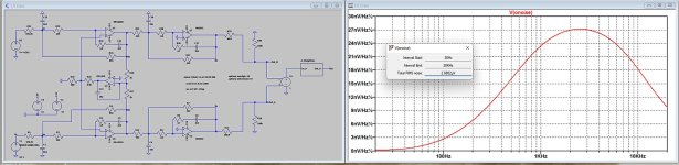
When simulating the filter that you use, with OPA2210 and NE5532, I measure a A weighted noise level of 2.6882uVrms.
There are many things where LTspice is not as accurate, but with noise measurements it excels.
All the right Voltage and Current noise figures, including their knee frequencies, were used as from the specs.
Taking 20*log(2.6882e-6/1.924) gives a S/N of -117.1 dB(A).
But this is the reconstruction filter only, without the added noise generated by the DAC.
So with a measured -116.8dB(A) and practically the same noise level visible in all 3 images in #1090, it almost seems as if some some calculation from filter bin width to broadband noise has a factor that is incorrect.
Hans
P.S. just to check, what happens to the measured noise level when taking a FFT size of 32,768.
I'm trying to understand the noise figures that you measured.
The 0dB output from the RTZ Firdac that I had, measured 1.924Vrms on the balanced outputs.
When simulating the filter that you use, with OPA2210 and NE5532, I measure a A weighted noise level of 2.6882uVrms.
There are many things where LTspice is not as accurate, but with noise measurements it excels.
All the right Voltage and Current noise figures, including their knee frequencies, were used as from the specs.
Taking 20*log(2.6882e-6/1.924) gives a S/N of -117.1 dB(A).
But this is the reconstruction filter only, without the added noise generated by the DAC.
So with a measured -116.8dB(A) and practically the same noise level visible in all 3 images in #1090, it almost seems as if some some calculation from filter bin width to broadband noise has a factor that is incorrect.
Hans
P.S. just to check, what happens to the measured noise level when taking a FFT size of 32,768.
Attachments
Last edited:
As I said on post #1102 my filter stage has higher gain so 0dBFS results in about 4Vrms. Not that it necessarily matters for noise on my board the filter stage uses OPA1678s instead of NE5532s.
Here is SNR measurement (i.e. dac playing silence) with 32k FFT. Result is more or less the same. As I said before most SW I've used has been able to calculate SNR correctly regardless of FFT window or size.

Here is SNR measurement (i.e. dac playing silence) with 32k FFT. Result is more or less the same. As I said before most SW I've used has been able to calculate SNR correctly regardless of FFT window or size.
With -118 dBFS(A) with 101010... patterns ( https://www.diyaudio.com/community/threads/return-to-zero-shift-register-firdac.379406/post-7417817 ) and -116.8 dBFS(A) with normal silence ( https://www.diyaudio.com/community/threads/return-to-zero-shift-register-firdac.379406/post-7419240 ), it looks like the filter dominates the noise floor, although there is also a difference between the ADCs and the clock generation.
Here is another SNR measurement. This time I used fixed 0x6969 data (set in MCU) which is supposed to be DSD silence although I'm not sure that applies to RTZ.

@nautibuoy The filter board sent to Acko is unmodified. Why would he be sent a version that three people already found to have inferior sound?During the weekend I found some time to disassemble my DAC and bypass the last op-amp stage and the coupling caps as suggested.
The obvious confirmed, (not so obvious until Hans Polak revealed that).
The already organic and smooth sound of this DAC is much better now.
Just trying to understand. The sound is inferior to Andrea's dac, and this is likely one fairly obvious possible cause.
Thx for trying.
So obviously the size of the FFT does not influence the S/N.
I don't know at what point in your filter you changed the gain, but the most effective point would be to change the 845R around the OPA2210 to 1k75, and to change the 2n2 to 1n2 for keeping the FR as flat as before.
With these changes including OPA1678 , I get a S/N of -120.3dB(A) just for the reconstruction filter.
When subtracting this noise value from the measured -116.8dB(A) for (DAC + Reconstruction Filter), this calculates into -119,4dB(A) for the Dac alone.
Hans
The filter in #1116, gives 2.2dB more noise as changing the gain at the first stage.
Now 0dBFS is 3.767Vrms and noise is 4.7048uV(A)
S/N then becomes 118.1dB(A) for the reconstruction filter, so with the measured -116.8dB(A) for the combo, this calculates into -122.7dB(A) for the Dac alone.
Hans
Now 0dBFS is 3.767Vrms and noise is 4.7048uV(A)
S/N then becomes 118.1dB(A) for the reconstruction filter, so with the measured -116.8dB(A) for the combo, this calculates into -122.7dB(A) for the Dac alone.
Hans
Thanks, I need to try your suggestion. I don't normally simulate noise with LTSpice as not all models include noise.
Just tried the last filter stage bypass mod.
Sound is a little more bright/clear, instruments are bit more separated from each other, soundstage is slightly wider than the speakers, imaging is improved some, and some but not all of the blur/smear is gone.
One more improvement. Moved slightly closer to Andrea's dac sound.
Sound is a little more bright/clear, instruments are bit more separated from each other, soundstage is slightly wider than the speakers, imaging is improved some, and some but not all of the blur/smear is gone.
One more improvement. Moved slightly closer to Andrea's dac sound.
Last edited:
Chances are that the filter of post #1116 distorts a bit less than one with doubled gain in the first stage. At least the first stage will distort less due to the smaller signal levels at its output and the higher loop gain due to stronger negative feedback. I have no idea how large or small the difference will be.
Last edited:
- Home
- Source & Line
- Digital Line Level
- Return-to-zero shift register FIRDAC