would Murata’s GJ8 series be any good ?
Depends what application and what dielectric. These are generally X7R, X5R.
I would only use them in high frequency (> 100kHz) switching power supplies, where you commonly need many large SMD ceramic capacitors to filter the power lines. Their nonlinear value with applied DC must be accounted for.
Thor

Well, doing that is usually a bad idea, if common.
Commercially it isn't. 25 years ago we usually had a BiCMOS chip with the radio receiver, separate ADC and DAC chips and a separate CMOS DSP. Nowadays you can have all of it on one CMOS chip at a fraction of the board area and costs, so no one would buy the old approach anymore.
Which is why I tend to use a small C0G next to the pin's (which ideally are next to the pin we close the loop to) and a "big old" (1210) film cap also close by.
That's exactly the kind of loop I meant, but with just the NP0 capacitor right next to the pins. We did an experiment with a 01005 capacitor glued on the chip and bonded straight to the bondpads with the shortest possible wires and that much improved things, but it was a bit impractical.
It was a serious effort to get past the "tech support" who kept pointing me to the datasheet and kept reiterating what was written there to the actual IC designer who luckily still worked there.
I'm surprised you managed to do that. I've never been in direct contact with anyone building equipment with an IC I worked on. I do get occasional questions from application and tech support people, when they have a complaint from a customer and they can't figure it out themselves.
His dry reply was "that's how it was designed" and my enquiry why it was not in the datasheet resulted in a bit of unprintable stuff about field support and application people.
The application people I know usually make sure that datasheets and application notes are reviewed by the IC designers.
Here a quick sim of my recommendation
4 X 1206 470n C0G
1 X 2220 100uF Pos-Cap (can use more)
4 X (series parallel) 8mm X 11mm 3F/2.7V Elna Dynacap DU
How do you model the losses? There must be damping resistances hidden somewhere, otherwise the impedance would alternately go to infinity and to zero at the various resonant frequencies and certainly not have a flat part of more than two decades. 60 mΩ ESR in C6, about 12 mΩ in C5, about 7 mΩ each in C1...C4?
Why do you draw the inductances explicitly and the resistances not? Is it a peculiarity of the simulator, that you can just fill in the ESR of a capacitor but not the ESL?
How do you model the losses?
Resistive part of the inductor model (not displayed).
Why do you draw the inductances explicitly and the resistances not? Is it a peculiarity of the simulator, that you can just fill in the ESR of a capacitor but not the ESL?
Actually, I can fill in ESR for inductors and RP for capacitors.
But yes, peculiarity of sim and me being lazy. I'm NOT trying to teach electronics or pass a test.
Mind you, this is still just first order simulation. I could fire up other stuff and download the S-Parameter models, but I found for my own use classic lumped LRC is adequate.
Thor
Last edited:
Commercially it isn't. 25 years ago we usually had a BiCMOS chip with the radio receiver, separate ADC and DAC chips and a separate CMOS DSP. Nowadays you can have all of it on one CMOS chip at a fraction of the board area and costs, so no one would buy the old approach anymore.
For many non-audio applications this is fine.
That's exactly the kind of loop I meant, but with just the NP0 capacitor right next to the pins. We did an experiment with a 01005 capacitor glued on the chip and bonded straight to the bondpads with the shortest possible wires and that much improved things, but it was a bit impractical.
If using a TSSOP or smaller package with the pin pairs next to each other we can get good loop performance, at least for 50MHz maximum clock speeds.
I'm surprised you managed to do that. I've never been in direct contact with anyone building equipment with an IC I worked on. I do get occasional questions from application and tech support people, when they have a complaint from a customer and they can't figure it out themselves.
It was a smaller manufacturer, quite innovative, since acquired by a major. I got e-mails relayed via a senior support guy.
The application people I know usually make sure that datasheets and application notes are reviewed by the IC designers.
We did not have a huge exchange. I suspect the IC designer was told that "just connect all GND Pin's and all Vcc Pin's together, like on EVM Fixture would give data sheet performance and make sure no customer messed up.
What I did certainly had potential for trouble. But the IC produced 3V inro 32 Ohm with ~ -100dB THD and ~114dB SNR at sub 50 cent in 1kU. Once fully optimised the IC performed extremely well, both objective and subjective.
It was also possible link up multiple IC's as balanced HPA with Charge pumps paralleled, to get significantly higher power levels.
Anyway I understand why designers want to take any control over circuit performance away from the customer. Sadly often cost and die size means trade-offs on passives end up being possibly different from what the customer would prefer.
So in my case, with this specific part the lack of such ability to "optimise" their IC's in a similar way meant a socket loss across 10's of products and 10+kU's on most. Which I appreciate is nothing to the likes of TI etc.
Thor
... try to see if an optimized version of my PWM8 modulator could be squeezed in a Spartan 6 LX9 FPGA.
I made some progress with this. It is still far from finished, but so far, it looks like two PWM8 modulators and a two-channel FIR filter can fit in an XC6SLX9-3TQG144C (or XC6SLX9-3TQG144I, if you want it to keep working when it freezes).
When I designed the digital sigma-delta modulator of my valve DAC, I knew some things about the theory of sigma-delta modulators and I had experience with the analogue parts of sigma-delta ADCs and DACs, but I had no experience whatsoever with FPGAs or with writing Verilog code. I therefore concentrated on getting it to work, rather than on optimizing things for small area.
Having another look, you can optimize it by kicking out the PWM4 and chaotic modes and doing the calculations for the five integrators - or more accurately, accumulators - serially rather than in parallel. The clock frequency then has to be multiplied by five, but that is no big deal, there are clock multipliers on the FPGA and the logic is fast enough. Instead of each having a dedicated register, the accumulator states are then kept in a kind of shift-register-like construction, which can also be used to pipeline some things.
The resonator feedback coefficients can be rounded to powers of two, the notches of the noise transfer function then actually get closer to the frequencies I originally intended. State variable limiting can also be rounded to powers of two.
Instantiating two of these sigma-delta modulators and two XORSHIFT128+ pseudo-random number generators on a XC6SLX9-3TQG144C, I get this utilization and no timing problems:
The interpolation filter of the valve DAC versions 1 up to and including 2.1 had to have a very good stopband rejection because of poor frequency planning: the quantizer could cause aliases if the images were not suppressed. I fixed that in version 3. In this case, the PWM8 modulator cannot cause aliases as long as the sigma-delta sample rate is an integer multiple of 8 times the input sample rate, which will normally always be the case.
When I then generate the coefficients for a 1024-tap interpolation filter using the Parks-McClellan program, use the Xilinx FIR compiler 5.0 to turn them into a two-channel, 8 times interpolating FIR filter (a chain of filters may be more efficient, haven't tried that) and add some stuff to round the output with dither, I get this:
Everything still fits in the XC6SLX9. There are set-up timing violations now, but as they are all related to the same register, I hope I can solve them with some pipelining.
Still missing:
-Input I2S interface
-Apodizing filter coefficient set, if space allows
-Clean timing
-Most importantly: proof that it actually works. I haven't tried or simulated it yet, I have only run an implementation in Pascal
See the attached zip file for the source code of the sigma-delta modulator.
Attachments
Forgot a few missing things:
-Double flip-flop synchronizers for the reset and other asynchronous signals
-Something to ensure it doesn't hang up when the master clock is switched, not even when this causes a spike
-Double flip-flop synchronizers for the reset and other asynchronous signals
-Something to ensure it doesn't hang up when the master clock is switched, not even when this causes a spike
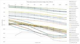
Here's an interesting test about distortions in resistors: Resistor Thermal Distortion Measurement
The melf MMU0102 MMA0240 and thin film ERA6A RR1220P are among the best
To make this image more readable/interactive you can use in Paint.Net the "Magic Wand" tool, set "Flood Mode" to global, Tolerance to 12%
Click on a line in the graph and the same color in the legend will also be selected.
The melf MMU0102 MMA0240 and thin film ERA6A RR1220P are among the best
To make this image more readable/interactive you can use in Paint.Net the "Magic Wand" tool, set "Flood Mode" to global, Tolerance to 12%
Click on a line in the graph and the same color in the legend will also be selected.
Attachments

Are you the seller of paint.net?
Paint.net is a free download. Free as in free beer. And free speech (which is not some far right conspiracy but the foundation stone of our democracies).
Paint.NET - Article From Wikipedia, the free encyclopedia
It is personally my go to tool for dealing with quick image editing, in preference to Photoshop. Photoshop get's used when paint.net is out of it's depth.
Thor
Free like this:

Okay, I now see there is a free download also. It is at: https://www.dotpdn.com/downloads/pdn.html
Okay, I now see there is a free download also. It is at: https://www.dotpdn.com/downloads/pdn.html
Free like this:
Are you on the microsoft store? Why?
Free here:
https://getpaint.net/download.html#download
Minus Mickeysoft store Tax.
Thor
Nope, just a happy user of the free available Paint.netAre you the seller of paint.net?
Hi Marcel
I am waiting for boards and components to make a version of your RTZ FIRDAC.
As PS for this I would very much like to use LIFEPO4 batteries and avoid all LDO´s.
3,3V is no problem as this is the nominal voltage of one LIFEPO4 cell.
5 V is a little trickier , but as I see it in the data sheets of the 5 V logic, all has a max voltage of 7V and the nominal voltage of 2xLIFEPO4 is 6,6V,. Of cause there has to be some monitoring of the voltage , so it is prevented from deliver MORE than 7V, but that is not difficult.
+/- 15 V for the reference and filter section I guess I can use 16,6 V instead from 5x LIFEPO4 cells as the max. voltage for OPA2210 is +/- 20V.
Any comments to this?
Hi Jesper
Do you know if LiTO is as quiet as LIFEPO4?
LIFEPO4 seams to be the preferred for direct battery PS for audio circuits. I have very good experience with them and they are very easy to charge too.
Thanks for chiming in..
Do you know if LiTO is as quiet as LIFEPO4?
LIFEPO4 seams to be the preferred for direct battery PS for audio circuits. I have very good experience with them and they are very easy to charge too.
Thanks for chiming in..
Hi Karsten - you are welcome ...
In my experience LiTOs are as quiet as LiFEPO4s. But I have only listened to the "square box" version made by Toshiba (2.4 Ah, 2.4V, IIRC) with a 1 mohm internal resistance. I do not have experience with other LiTO batteries but I would expect all of these Li battery types (with a certain capacity) to have noise levels that are close to immeasurable in practice.
Regarding preferred batteries for audio I have some A123 LiFEPO4s (26... can size) and compared with a couple of Li-ion battery models they do sound differently. However, my personal guess is that SQ/preference likely may be dependent on the actual battery model, in the actual circuit, etc., etc. ... I reckon you know where this may go 😉
Cheers, Jesper
Marcel.
Another question. Did you ever try the passive filter you made for yor tube dac in the RTZ-FIRDAC?
If it is ok to use that, would it be possible to make a buffer stage after the FIRDAC and reduce the impedance of the filter and then use a Sowter 1465e as output/step-up transformer.
https://www.sowter.co.uk/specs/1465.php.
With the secondary's in parallel and the ratio is 1:5, maybe that is too high output level, so I could perhaps use the filter as single ended and serie couple the primary?
In fact this is one of the audio mysteries, at least to me.Regarding preferred batteries for audio I have some A123 LiFEPO4s (26... can size) and compared with a couple of Li-ion battery models they do sound differently. However, my personal guess is that SQ/preference likely may be dependent on the actual battery model, in the actual circuit, etc., etc. ... I reckon you know where this may go 😉
Every different supply, as different types of batteries, different voltage regulators, all change the perceived sound to my subjective opinion.
But this is indeed a topic that could lead to endless and non converging discussions, so better be avoided.
Hans
- Home
- Source & Line
- Digital Line Level
- Return-to-zero shift register FIRDAC