Yes, but this is a diy forum. Suppose someone were selling amplifier boards named after some furry, low-to-the-ground animal, with claws and a snout, and perhaps known to inhabit the California Foothills. All you need is a power a supply and case to rival the best commercial amps ever made. Should you be concerned about EMI/RFI ingress or not?And yes, in a correctly designed and bandwidth limited analogue linear amplifier it is possible to avoid to actualising the resulting risks.
not all new and upcoming builders have time and ears to qualify their builds. Take me, for some part, into this camp.
Not the time then, I guess. I know from past encounters that there is nothing wrong with your ears.
When it comes to signal processing in the electrical domain - just skip any human aspect of it. Once a full definition can be made of an electrical signal, a proper quest (i.e. requirement) for the perfect DAC, AMP etc. can be made. Probably something is missing in our usual measurements arsenal, but there is probably also something missing in its interpretation. Maybe the dB scale is the hoax...convinenient yes but it might also lead us on a wrong track... It's like; once one come up with the correct question, the solution is not far away. Because we are not designing against hearing thresholds... right!?
//
//
Well, that’s excactly what made me construct a bridge between DSD file and LTSpice, which will enable me to play a real .dsf files over the Firdac and Filter module in LTSpice.
This may or may not shed some light on things like aliasing or whatever could be causing anomalies.
In LTSpice it’s much easier to investigate these things and to compare results with the measured recordings while using the same .dsf files.
I did the first run today and the model is working properly
Will comeback when results are ready to show.
So instead of talking about possible problems this is hands on.
Hans
Accurately simulating low-level artefacts in sigma-delta DACs and ADCs is generally difficult. You need tight accuracy settings and insane run times to get anywhere near the resolution of bohrok2610's measurements and you also need models of the components and PCB that are accurate enough up to quite high frequencies.
You made me laugh wholeheartedly. 😀 From past encounters I know it is a pleasure to work with you.Not the time then, I guess. I know from past encounters that there is nothing wrong with your ears.
EDIT: going to bed now. maybe there will be a response to all previous answers to my posts, clarifying my intents.
Last edited:
Very true, but there is a small chance that something pops up in this experiment that could lead to an explanation for those weird spectral lines, so why not giving it a try ?Accurately simulating low-level artefacts in sigma-delta DACs and ADCs is generally difficult. You need tight accuracy settings and insane run times to get anywhere near the resolution of bohrok2610's measurements and you also need models of the components and PCB that are accurate enough up to quite high frequencies.
This model comes as close as realistically possible to the real world, but certainly has its limits.
Hans
P.s. this model has also its benefits because it evades all possible side effect as crosstalk, reflections, Vref modulation and whatsoever.
It purely concentrates on the basics.
Last edited:
Yes, but this is a diy forum. Suppose someone were selling amplifier boards named after some furry, low-to-the-ground animal, with claws and a snout, and perhaps known to inhabit the California Foothills. All you need is a power a supply and case to rival the best commercial amps ever made.
Sure. Mind you, if you mention said Animal, what comes to my mind is this:
The AAC Honey Badger. Characterised by improved SNR over other AR pattern rifles.
I'm not a fan of the AR platform in general, except perhaps in .300 BO (which you cannot get in any platform I like). Even then I probably prefer something different, I really don't like plastic furniture on guns. Shame we cannot easily get the VSSM Thread cutter in .38 rus.
But yes, it beats every amplifier under the sun. And Sus Scrofa is known mainly for aerobatics.
I think I know the Amplifier you refer to, no doubt it is perfectly acceptable and will outperform many a Class D unit. But a Self Blameless Clown is not a great amplifier, merely good.
I'd venture the 1989 Model Year Super AA Amplifier in my AV and music room (driving Technics SB-E100) is a better amplifier.
It is not possible for anything to be the best amplifier in the world, that was already claimed for an amplifier that is a Clown of a Swiss amplifier by a Hungarian named after a boy who was sent to a monastery and got into a life of art and debauchery...
Speaking of Hungarians,
Should you be concerned about EMI/RFI ingress or not?
I don't know, I didn't' buy the board. But the input anti EMI/RFI etc. measures consist of a first order lowpass at 718kHz. I don't think the -3dB OLG corner is at 1.4MHz and I suspect that the knee of the rising HD curve with is at likely 1/100'th of less than the input lowpass.
Now the key question is, does it matter that if suitable EMI/RFI is present, that it is not filtered? Answers on a postcard.
Personally I think most of the perceived differences in sound quality between amplifiers that have sufficiently low harmonic distortion to be reliably inaudible (which is not all that low HD/THD actually) relate to the behaviour of the amplifier in unintended or insufficiently considered circumstances.
Be it EMI leakage into the Amplifier, clipping behaviour, thermal memory of the Class AB output stage, thermal memory of earlier stages, non-linear parasitic etc. leading to subtle differences in signal fidelity that remain audible despite being well below the actual HD.
Of course that is just my pet theory. And given that most audio electronic these days uses variations of the base circuit also expressed by a Self "Blameless" Amplifier, if my Pet Theory has a basis in reality, that's quite a bind.
Life is not made easier by the human propensity to hear what we expect. It makes listening tests (including blind and ABX) rather challenging.
A team of neuroscientists of TU Dresden headed by Prof Katharina von Kriegstein presents new findings that show that not only the cerebral cortex, but the entire auditory pathway, represents sounds according to prior expectations.
Thor
When it comes to signal processing in the electrical domain - just skip any human aspect of it.
This is the dichotomy between signal fidelity and audible fidelity impairments. There is little of any reliable link between these, once a base level where the reduced signal fidelity impairment no longer corresponds with a perceived reduction in audible fidelity impairment.
Once a full definition can be made of an electrical signal, a proper quest (i.e. requirement) for the perfect DAC, AMP etc. can be made.
This is a philosophical fallacy often known as the Platonic philosophically ideal chicken coop, complete with philosophically ideal chicken sh!t. And it is followed by the implication that if we cannot make something ideal or perfect, then making something that is as close to the philosophical ideal is the correct course of action.
Probably something is missing in our usual measurements arsenal, but there is probably also something missing in its interpretation.
I think mostly what is missing is on the interpretative side. We generate so much data these days, about the behaviour of audio gear and thanks to the Cargo Cult of SINAD, Stereophile, Soundtstage etc. we have immense amounts of data on the objective behavious of audio gear.
With items like Quantasylum Analyser, Kosmos ADC and the advent of dirt cheap 100MHz+ multichannel oscilloscopes, every hobbyist should find it trivial to add to the data. We are not plagued by a dearth of data, as we were in the 80'sand 90's of the last century of the previous Millenium.
Maybe the dB scale is the hoax...convinenient yes but it might also lead us on a wrong track...
It is not a hoax, it is a convenient simplification of a complex mathematical relationship, in a time when a room full of "Computers" looked like this:
NACA High Speed Flight Station "Computer Room" (1949)
It's like; once one come up with the correct question, the solution is not far away.
Agreed.
Because we are not designing against hearing thresholds... right!?
Why not? I always do. I consider the audibility and then leave some extra "footroom" and then look at other issues.
Any other approach seems pointless. Why spend time, resources and effort on something that has no audible impact or possibly a negative one, instead of focusing on things that allow us to make improvements in audible fidelity?
Thor
But all the impact of these reasons for errors show up in the DUT external interface as good ol' level, time, distortion and/or noise - so we know how to measure. So its "just" to specify the correct external conditions (drive, load, EMI, heat, vibration (pre/during), power) to trigger all these aspects while measuring the DUT.Be it EMI leakage into the Amplifier, clipping behaviour, thermal memory of the Class AB output stage, thermal memory of earlier stages, non-linear parasitic etc. leading to subtle differences in signal fidelity that remain audible despite being well below the actual HD.
But maybe the analysis need to go to actual signal "envelop" level - averaging methods just don't do it? Also the stimuli might be in need of scrutinisation...
More science, more accurate models, higher ambition, more deep tiresome job....
You truly clever guys take a holistic stab at it as @Tfive says....
//
Last edited:
But all the impact of these reasons for errors show up in the DUT external interface as good ol' level, time, distortion and/or noise - so we know how to measure.
Note, I stated we had a lot of data and the interpretation was lacking.
So its "just" to specify the correct external conditions (drive, load, EMI, heat, vibration (pre/during), power) to trigger all these aspects while measuring the DUT.
Funny thing, I suggested the opposite to one of the measurement guys, who was measuring hum that was the result of a lack of an earth connection on the DUT and the limited CMRR of his analysers floating balanced input (actually a cousin of what we have been debating in the DAC filter) and thus was not real, he refused to give "special treatment" to the device.
My conclusion was that even if you tell these people how to measure it, they will ignore you. Those who are REALLY interested already know how to measure this stuff anyway.
But maybe the analysis need to go to actual signal "envelop" level - averaging methods just don't do it?
Averaging tends average out random events, that's why we do it. But it can also hide things as a result. Or rather attenuate them.
Also the stimuli might be in need of scrutinisation...
I think it starts by understanding how humans hear and what they hear.
And then to consider how electronic recording alters the acoustic event compared to actually sitting in an auditorium and to define what we are trying to achieve.
More science, more accurate models, higher ambition, more deep tiresome job....
And you think that will create a better audio system? And what is "better" in the context, what do we mean by "better". Should we not first define that?
Thor
Just some info's I wanted to share.
I did some calculations on the DSD transfer rates and was surprised by the huge amount of processing in a restricted amount of time and also by the lack of markers within the .dsf file.
A .dsf file has a header of 91 bytes, telling all sort things like DSD rate, file length and other parameters.
The data starts as from position 92, where 4096 byte blocks are alternating for the Left and the Right channel.
Each byte in the data stream has to be reversed, so 0111 0001 becomes 1000 1110.
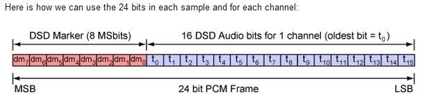
When I'm right, when sending DSD over DoP, to each set of 16 DSD bits, eight additional PCM marker bits are added to get a 24bit PCM frame.
This increases speed by 24/16 or a factor 1.5 giving a transfer frequency for DSD64 of 8.467,200 Mhz (or PCM 176,400 Khz) and for DSD512 over PCM of 67.737,600 Mhz (or PCM 1.411,200 Mhz).
The converter will have a complex job in extracting the 16 DSD bits from each frame, reversing the bytes, storing a 4096 byte block to get the left and the right channel bits released at the correct parallel time and to produce a stable bitclock.
A bitclock for DSD64 is at 2.822400 Mhz and for DSD512 at 22.579,200 Mhz leaving in that case ca. 44nsec processing time for each set of output signals while doing the whole job as described.
So it seems almost not as a surprise that the Amanero is not fit for that demanding job at DSD512, resulting in a flawed channel and substantially more noise, because possibly several bits are not properly recorded and/or stored or because of internal crosstalk problems.
Also when somewhere in the process the selection of the 4K byte blocks gets shifted, parts of one channel will get into the other channel which will lead to strange anomalies.
I won't say his this is the case here, but a DSD file has no marker "end of 4K block" or "start of 4K block", nor does it tell that it concerns Left or Right.
When the synchronization gets lost somewhere, it will proceed until the end.
Hans
I did some calculations on the DSD transfer rates and was surprised by the huge amount of processing in a restricted amount of time and also by the lack of markers within the .dsf file.
A .dsf file has a header of 91 bytes, telling all sort things like DSD rate, file length and other parameters.
The data starts as from position 92, where 4096 byte blocks are alternating for the Left and the Right channel.
Each byte in the data stream has to be reversed, so 0111 0001 becomes 1000 1110.
When I'm right, when sending DSD over DoP, to each set of 16 DSD bits, eight additional PCM marker bits are added to get a 24bit PCM frame.
This increases speed by 24/16 or a factor 1.5 giving a transfer frequency for DSD64 of 8.467,200 Mhz (or PCM 176,400 Khz) and for DSD512 over PCM of 67.737,600 Mhz (or PCM 1.411,200 Mhz).
The converter will have a complex job in extracting the 16 DSD bits from each frame, reversing the bytes, storing a 4096 byte block to get the left and the right channel bits released at the correct parallel time and to produce a stable bitclock.
A bitclock for DSD64 is at 2.822400 Mhz and for DSD512 at 22.579,200 Mhz leaving in that case ca. 44nsec processing time for each set of output signals while doing the whole job as described.
So it seems almost not as a surprise that the Amanero is not fit for that demanding job at DSD512, resulting in a flawed channel and substantially more noise, because possibly several bits are not properly recorded and/or stored or because of internal crosstalk problems.
Also when somewhere in the process the selection of the 4K byte blocks gets shifted, parts of one channel will get into the other channel which will lead to strange anomalies.
I won't say his this is the case here, but a DSD file has no marker "end of 4K block" or "start of 4K block", nor does it tell that it concerns Left or Right.
When the synchronization gets lost somewhere, it will proceed until the end.
Hans
Last edited:

Because we are not designing against hearing thresholds... right!?
//
Because we don't the know the audible thresholds - or they differ between individuals so an uncertain and moving target. Those are hard to hit.....
Why not? I always do. I consider the audibility and then leave some extra "footroom" and then look at other issues.
....
Thor
//
This is where we don't agree. For speaker design in normal living room I can accept this stance but I simply see no reason for this in electronics...I think it starts by understanding how humans hear and what they hear.
//
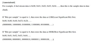
In DSF file data is stored LSB first (if "bits per sample" = 1) so actually LSB is stored as MSB in data bytes. As data bytes are sent MSB first to DAC there is no need for reversing bits in bytes.Each byte in the data stream has to be reversed, so 0111 0001 becomes 1000 1110.
You may be right, but that’s not what the specs are telling.
As a matter of fact, in a 1 bit datastream there is no MSB or LSB. 🤣
As a matter of fact, in a 1 bit datastream there is no MSB or LSB. 🤣
I think the spec is quite clear on this. Below is annotation 4 from
https://dsd-guide.com/sites/default/files/white-papers/DSFFileFormatSpec_E.pdf
Besides as I have implemented USB-to-DSD interface I know there is no need for reversing bits in bytes 😉
What matters though is endianness.
https://dsd-guide.com/sites/default/files/white-papers/DSFFileFormatSpec_E.pdf
Besides as I have implemented USB-to-DSD interface I know there is no need for reversing bits in bytes 😉
What matters though is endianness.
Attachments
Last edited:
O.k. Thx.
In my .dsf files I have bits per sample 1.
So I read this as having to reverse all bytes, true ?
Hans
In my .dsf files I have bits per sample 1.
So I read this as having to reverse all bytes, true ?
Hans
I see what you are telling, but find this at least very confusing when looking at the specs.
Maybe others can give their opinion on this.
But thx anyway in paying attention to this item.
Hans
Maybe others can give their opinion on this.
But thx anyway in paying attention to this item.
Hans
- Home
- Source & Line
- Digital Line Level
- Return-to-zero shift register FIRDAC