Hi Martin,
Thank you for the reply.
In the mean time I replaced all capacitors in the power supply and others elco's in the audio circuitry.
The result is really excellent, a very dynamic sound, sweet highs, never harsh.
You mean that the new "A77" heads have a lower output than the original G36's ?
Best regards,
Kirikoo
Hello kirikoo,
I never liked the sound of the original playamplifier. But what do you expect from three ECC83 in a row? 😉
That´s why I built my own reproamplifier.
No. The new G36 head and the old head have the same output voltage. 3,8mV 1KHz 0dB 19cm/s 320nWb.
The A77/B77/A700 head has an output voltage of 1,9mV. 6dB less.
Best regards,
Martin
The result is really excellent, a very dynamic sound, sweet highs, never harsh.
I never liked the sound of the original playamplifier. But what do you expect from three ECC83 in a row? 😉
That´s why I built my own reproamplifier.
You mean that the new "A77" heads have a lower output than the original G36's ?
No. The new G36 head and the old head have the same output voltage. 3,8mV 1KHz 0dB 19cm/s 320nWb.
The A77/B77/A700 head has an output voltage of 1,9mV. 6dB less.
Best regards,
Martin
Hi kevin , can you describe in detail the procedure to change the ecc83 at the cathode follower output with a 12AT7?Depending on the input impedance of the device you are connecting your ReVox to all you may need to do is replace the output coupling caps with larger capacitance values. This should be ok if the input impedance is 47K or greater.
In the case where you are talking about 10K then your simplest recourse is a unity gain buffer using either an op-amp or a tube based cathode follower using something like a 5687. One other possibility would be to revise the CF in the ReVox's playback amplifier to use a 12AT7A and run that at a few mA higher than the stock 12AX7A in order to get the drive for low impedance loads. Note that if you do that the extra current has to come from somewhere, and the best place to get it is by deleting the speaker amplifier or the first two stages of the record amplifier. I've done both as I find neither particularly useful in this day and age - and those extra 2 stages ahead of the record level pots clip like crazy with modern digital sources. In addition the additional circuitry reduces transparency and is completely unnecessary with any modern source unless you plan to use dynamic mics with this deck, which I don't.
Transformers aren't really on for this application because the required impedances are high enough that the use of most affordable transformers will result in a loss of transparency, both leakage inductance and stray capacitance are major issues at this impedance. (Reflecting a 100K load impedance to the deck is non-trivial at these signal levels.)
How do I increase the mA? Please let me know. All the best Marco
Hi Marco,
I got rid of this recorder about 9 years ago so I really don't have anything to refer to at this point.
I got rid of this recorder about 9 years ago so I really don't have anything to refer to at this point.


Hi Volken,
Although I have moved on there may be some interest here in what you are doing. I would post some details to gauge interest. I'm certainly curious.. 😀
Although I have moved on there may be some interest here in what you are doing. I would post some details to gauge interest. I'm certainly curious.. 😀
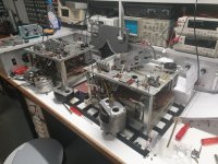
Two G36 recorders one a low speed the other HS for modify the LS to HS the motor chassis mounting needed some modification too.
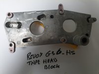
Seen at the second picture the headstack original factory modification with larger holes , needed because the shaft size is two times the ls .
To keep a good tape contact with the PB head the motor is placed a bit to the back.
The two chassis pictures show the LS version and HS with endlarged holes
Seen at the second picture the headstack original factory modification with larger holes , needed because the shaft size is two times the ls .
To keep a good tape contact with the PB head the motor is placed a bit to the back.
The two chassis pictures show the LS version and HS with endlarged holes
Attachments

I did not realize the extent of mechanical modifications required, but on reflection moving the capstan motor to compensate for the much larger capstan diameter makes sense. Wow! 😀
Hi all,
I've been reading here about changing the Revox G36 from Low Speed to High Speed, how the capstan motor works with frequency, I've been thinking if I can't increase (controller) its speed by frequency, like I do with my record player's motors, It would be possible to double your speed without changing the capstan. So please, I would like to know, is this torque issue really an unsolved problem for G36 owners who would like to change their machines to HS?
Paulo
Hi since I drive my capstan motor now with a three-phase powersupply I will try this soon .
There are probably some issues concerning the torque and the needed higher drive voltage but we will see.
There are probably some issues concerning the torque and the needed higher drive voltage but we will see.
If you double the frequency of the supply the impedance of the motor windings will be so high it will not have sufficient torque to run up to synchronous speed. If you then increase the supply voltage to overcome this problem you will be operating the motor far outside it`s design ratings and failure of the insulation is likely.
Speed variation of a synchronous motor is sensibly possible over perhaps +/- 25%, not much more.
Speed variation of a synchronous motor is sensibly possible over perhaps +/- 25%, not much more.
Thank you @barrymagrec
I understand. I imagined that the motor capstan had a gap in its RPM limit, many turntable motors can vary from 331/3 to 78rpm. That's bad, it's very difficult to get an original capstan for the G36 HS.
I understand. I imagined that the motor capstan had a gap in its RPM limit, many turntable motors can vary from 331/3 to 78rpm. That's bad, it's very difficult to get an original capstan for the G36 HS.
Hi @volken
I'm interested in your progress with the G36 changes.
Can I change to "three-phase powersupply" on the original capstan engine of the G36? Is it the same as in turntable engines?

Yes the G36 motor is a three-phase motor just as most Papst motors are. I made a pcb as replacement for the old speed switch , with the option to connect a three-phase supply to it ,the phase caps need to removed then .
Yes with shaded pole motors I can confirm this but measurements on the Papstmotor shows no significant increase.If you double the frequency of the supply the impedance of the motor windings will be so high it will not have sufficient torque to run up to synchronous speed. If you then increase the supply voltage to overcome this problem you will be operating the motor far outside it`s design ratings and failure of the insulation is likely.
Speed variation of a synchronous motor is sensibly possible over perhaps +/- 25%, not much more.
"Yes with shaded pole motors I can confirm this but measurements on the Papstmotor shows no significant increase."
Yay! I will be very happy when I see the result.
Just curious, isn't there another Capstan Motor with more torque, that can precisely replace the original G36?
Yay! I will be very happy when I see the result.
Just curious, isn't there another Capstan Motor with more torque, that can precisely replace the original G36?
Yes same supply that I build for the EMT 930-927 turntable@volken
If the capacitors are removed, then will your new power supply drive a three-phase = 0, 120, 240 degree synchronous motors, like those in my turntable, however, without varying the rotation, correct?
Why another motor that motor is perfect and with three-phase drive you get more torque then single phase , but thats not important the 100hz flutter sideband is gone so is the stator vibration.

I'm already in the process of assembling the SG4, when it's ready I'll also try it with the capstan motor from the G36, and also from the A77.
- Home
- Source & Line
- Analogue Source
- Restoring ReVox G36 MKIII - Expert Opinions Solicited