There are some situations where mounting smd capacitors standing up on their narrow edge improves performance.
Eh, how, never mind the soldering problems?
So do we accept that orientation of a multiplate capacitor can change the performance?
Can we apply that knowledge and ask the question:
Would a folded foil resistor perform differently depending on whether the resistor is flat on the PCB, or standing on edge?
And which edge should face the PCB?
We already know that orientation of a linear resistor, be it a single helical coil, or a straight resistive element, can perform differently.
Last edited:
So do we accept that orientation of a multiplate capacitor can change the performance?
Can we apply that knowledge and ask the question:
Would a folded foil resistor perform differently depending on whether the resistor is flat on the PCB, or standing on edge?
And which edge should face the PCB?
We accept you quote things completely out of context without back up information.
Decoupling PSUs in the GHz region is not a problem audio amps generally have to worry about. And any RF engineer I had working for me at the time who suggested putting Capacitors on their sides would have been send back to design the circuit properly so it could be manufactured.
In theory I am sure you could change parasitic capacitance of a tin foil Resistor, but if it matters under 20KHz you have a big problem. More of an issue is that bulk foil resistors are strain gauges.
No **** different capacitors have different parameters. Even Doug self will admit that in 'certain' cases there are capacitors you just don't chose.
https://www.youtube.com/watch?v=f_zkE_42BV4 If you have some time to learn something.
Or this: Cyril Bateman's Capacitor Sound articles | Linear Audio NL
Or his latest article in Linear Audio: Linear Audio | your tech audio resource
Jan
I stand by my comment. Martin C, who despite being a designer of some well accepted loudspeakers does go completely bonkers on occasion.
For example on the Holco he says
"
Sound 88%: a very fair copy- neutral, well balanced, clear and clean strings, good depth, slightly soft bass, very mildly defocused, accurate."
A copy of what? There was no reference as this was a cartridge load and CD player output termination, not only that but it was in parallel with another resistor. Its flooby dust at its worst. No measurements of the LCR and no measurements of the system.
If you wish to believe that this has given a valid data point, fine, but to me its a journo getting his fee for faffing about a bit. Note that the wirewound resistor sounds 'wiry'. At least the bulk foils didn't sound 'crinkly'
I believe that the attachment you posted earlier and clearly refer to above was an abstract from a longer article; an article which I seem to remember did give at least some of the additional information which you state as lacking.
FDEGrove ... a seasoned head with a lot of experience of both music and sound systems is as usual totally correct - in my view that is!! (He is one of the very few members here whose preferred system I would really like to hear for myself) We should listen to him.
Just use these... or similar
http://www.mouser.com/ds/2/40/licc-776614.pdf
we are talking decoupling inductance, hence why we use 0201 packages a lot these days with high speed... But even these are of no use once you get above 20-40MHz.
Resistors are a different matter, different construction etc. don't have multiple plates to worry about, but also available in low inductance packages (0612 instead of 1206s I used them on a class D layout I did for someone to reduce parasitic inductance...
So there are low inductance packages available, mainly where the parasitic inductance is going to be a problem, this is usually very high speed designs, I don't see how this would equate to the low frequency analogue side of audio or whether I would use a MLCC in the analogue signal path (COG possibly).
Now as Bill has said, how would you actually mount MLCC capacitors on their edge in the real world of production, they are supplied flat in the tapes for a start off and picked up by a small vacuum head...
If anyone can find that reference I would like to see it. JC says it 'proves' something. Beyond the gullibility of HFN readers can't see what tho.I believe that the attachment you posted earlier and clearly refer to above was an abstract from a longer article; an article which I seem to remember did give at least some of the additional information which you state as lacking.
FDEGrove ... a seasoned head with a lot of experience of both music and sound systems is as usual totally correct - in my view that is!! (He is one of the very few members here whose preferred system I would really like to hear for myself) We should listen to him.
I don't see why. If someone comes up with something that is a personal experience with nothing to back it up I will call them up on it. No one should get a free ride just because they are 'well seasoned' (does that mean old or just a bit salty?)
I have a very few smd capacitors that are square in profile. 1uF and 10uF MLCC
They could have been installed flat, or on edge. I could not tell the difference and I certainly could not measure the difference in performance.
They could have been installed flat, or on edge. I could not tell the difference and I certainly could not measure the difference in performance.
MLCC caps started of pretty flat, and were initially available in low values well below 1uF, but as manufacturing techniques have improved and the need for small higher value caps with low ESR in the uF range has made production viable you now get taller MLCC caps with higher value... The higher values would not be used for local de-coupling next to a devices pins but for reservoir caps, so the parasitic inductance is not as critical as it is for the smaller values caps. 0201 and 0402 are the most popular package sizes for decoupling high speed these days, with the right footprint (IPC-7351) you can place them directly under a BGA device pads on the opposite side and use via in pad to further minimise parasitic inductance, or use 0201's on the same side as the BGA between the pins...
You can also get elevated temperature range MLCC caps (8R* series) flexi term for resistance to cracking, non-singing types for lap-top power supplies etc.
Same with resistors, there are many different types, different packaging so you can choose the correct device for a particular part of the circuitry.
Last edited:
Microphony at 2GHz would be very impressive to measure. And I doubt a chip cap pics up anything even if you hit it with a hammer. But I could understand if some boutique hand made by virgins capacitor made a good microphone.
It is microphonic at audio frequencies. Worse if there is DC across it. You don't need to hit it with a hammer. A shaker table will show it well. As there is a baseline of at least .05G (G as in Gravity) vibration everywhere you can easily see how much of an issue any part will be in a given circuit. Not surprisingly the larger and bulkier capacitors usually have less of an issue.
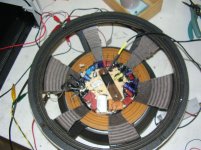
Attached are some results from ceramic capacitors and a picture of the test device. Note where the resonances occur, prime audio frequencies.
Excitation was as I recall a 9V battery with a 10K series resistor. Note this is different than the piezoelectric effect.
Attachments
Last edited:
Can't see any SMD caps on the test device. Can you point them out?
Not from then, but have noted the issue since then. Do you think it is the leads that matter? Did also test resistors and shorted leads.
It is just common sense that any capacitor construction must be microphonic as the dielectric and even the electrodes must have some deflection under the load of either the other layers or the substrate.
But please show your measurements.
You do understand the definition of capacitance is C=q/V which yields C dv/dt + V dC/dt = dq/dt = i.
There is a minute amount of dc/dt due to just applying voltage, most of it comes from vibration in real capacitors.
Not from then, but have noted the issue since then. Do you think it is the leads that matter? Did also test resistors and shorted leads.
It is just common sense that any capacitor construction must be microphonic as the dielectric and even the electrodes must have some deflection under the load of either the other layers or the substrate.
Just trying to understand if you were extrapolating or if you had experience with SMD MLCC microphony. I was confused as we were discussing MLCC and suddenly a pic of leaded caps was shown. Of course I accept that microphony exits in any 2 parallel plates with a potential across them. But designing around that and chosing the right components is just good design with no magic.
Attached are some results from ceramic capacitors and a picture of the test device. Note where the resonances occur, prime audio frequencies.
Made by Dave Davies? Carefully made piece of gear, how did you normalize out the local acceleration of the caps vs the accelerometer? Claiming uniform piston motion of this would be a bit much. Also the dangling leads are not as the capacitor is used.
Last edited:
wire is microfonics try putting on the floor a coax guitar cable ...
I think you are confusing wire with triboelectric effect which is due to the insulation and sheath.
caps have insulation and sheath too
What has that got to do with the fact that you don't know the difference between a wire and a cable?
Not from then, but have noted the issue since then. Do you think it is the leads that matter? Did also test resistors and shorted leads.
It is just common sense that any capacitor construction must be microphonic as the dielectric and even the electrodes must have some deflection under the load of either the other layers or the substrate.
But please show your measurements.
You do understand the definition of capacitance is C=q/V which yields C dv/dt + V dC/dt = dq/dt = i.
There is a minute amount of dc/dt due to just applying voltage, most of it comes from vibration in real capacitors.
Lots of equipment subjected to military level vibration tests use MLCCs, there is no effect on the circuit performance during vibration testing, though if you flick them with a finger when they are on a board you can get a spike, but it not a real world test (the finger flick). Of course your PCBs are not going to be fastened to a sub woofer...
And yes the leads do have an effect, SMD devices are held hard to the board so differential vibrations are limited.
- Status
- Not open for further replies.
- Home
- Member Areas
- The Lounge
- Resistor Sound Quality?