I have Vishay VSRT 743R300 0.01% in my storehouse.Their sound quality may be the best IMHO.Can i make potentiometer with them? I think i have about 100pcs in my storehouse,i should check ( i sold about 500of them in a very good price and now i am a bit regretful) If anyone knows a good quality step atteunator please tell me.
Member
Joined 2009
Paid Member
The trick from Audio Precision is using the same resistor for series as shunt, but use 20 in series to get to the 20x. In that way, all tempco and voltco effects are the same in each resistor and cancel out at the feedback point.
Jan
That's exactly what I would have expected but I guess it's an extra cost which most commercial amp builders simply won't accept.
FYI - I don't necessarily want to cancel out the resistor sound. One approach to all this DIY stuff is to design and build to minimize distortions and get as close to a 'wire with gain' as possible. I have found that I like a clean sounding amp. But a second approach is to take advantage of distortions to make a likeable amp. I've moved back and forth between these two camps and finally I find that there is a middle way which suits me best.
Amazing that someone finally(?) mentioned that a shunt resistor between a low output resistance DAC buffer and a preamp can't add more than a tiny amount of distortion (none if the DAC buffer has no output "safety" resistor).
I mentioned it three times in this thread.
Can i make potentiometer with them?
There are switched resistor volume control pages out there on the net. For one example: Resistor-Switch Attenuator Networks for Audio Volume Control
Seems like the main question is whether or not you could easily build a volume control with the resistor values you have in stock.
Last edited:
resistor values?
I have many different values of NOS Holco and Dale mil grade leaded,New Vishay thin film SMD and many kind of Vishay melf resistors.I also have thick film vishay resistors but i heard that it is not good to use them in audio.It seems low noise precision resistors should be selected.Maybe Vishay melf not common values of resistors would be a good choice in a good price.I should make a list of them because of log potentiometers need different type of resistors.
I have many different values of NOS Holco and Dale mil grade leaded,New Vishay thin film SMD and many kind of Vishay melf resistors.I also have thick film vishay resistors but i heard that it is not good to use them in audio.It seems low noise precision resistors should be selected.Maybe Vishay melf not common values of resistors would be a good choice in a good price.I should make a list of them because of log potentiometers need different type of resistors.
Also note the test resistors were 1W or 0.5W so for 22K we are talking not even a milliwatt at line levels. Do people even read what is posted (I know in this case it's hard)?
Thank you for pointing this out.
A properly selected resistor for a circuit (power and ambient temperature) will not exhibit any consequential thermal modulation by the signal. The thermal inertia will be too high to change the temperature fast enough to introduce anything but drift.
I have read that thermal modulation might be a contributing factor to distortion in chip amps. This claim has merit on theoretical grounds. The whole circuit is tiny and it's all in close proximity (low thermal resistance) so thermal modulation is hypothetically possible. Remember, in a discrete amplifier the input and output stages are not in close thermal contact; in a chip amp they are. So the difference in thermal hysteresis between discrete vs integrated would be significant. How consequential this is , I do not know. I also don't know if it has been investigated, either.
Infinitesimal is okay, just so long as people don't jump to conclusions that a very small effect is inaudible. If someone says they swap resistors and hear a difference then maybe they do and maybe they don't.
If there is an audible difference then there has to be a plausible physical explanation. If one takes Martin Mallinson not to be a liar, then ESS found out that humans can hear 'exquisitely' low levels of signal modulated noise. How many resistors are measured for that performance parameter? Also, what pathological circuit conditions might be sensitive to different resistor construction details?
My point is that there are plenty of things to think about before jumping to conclusions.
Spoken like a true snakeoil salesman.
When so many people think they can hear something it must be true? Like bybees and shatki stones. First prove people can hear the difference in shunt resistors, you cant. As Scott said the effects are at -180db.
Resistor noise modulation? Now your making stuff up.
Don´t be ridiculous. 😛Are standard 1/4W 1% metal film resistors sufficiently linear for Hall Notch filters for looking at distortion at -160 dBc?
Or for use in the PCM1794 I/V & filter?
Or the ES9038Q2M I/V & filter?
Or for use in Samuel Groner's Super Op Amp? Samuel Groner's super opamp
Thread is about extravagant claims about claimed gross sonic differences by using a resistor getting a few mV about it, driven from a lower source impedance and you introduce these absolutely irrelevant comparisons.
Are you serious?
Of course not.

Thank you for pointing this out.
A properly selected resistor for a circuit (power and ambient temperature) will not exhibit any consequential thermal modulation by the signal. The thermal inertia will be too high to change the temperature fast enough to introduce anything but drift.
I have read that thermal modulation might be a contributing factor to distortion in chip amps. This claim has merit on theoretical grounds. The whole circuit is tiny and it's all in close proximity (low thermal resistance) so thermal modulation is hypothetically possible. Remember, in a discrete amplifier the input and output stages are not in close thermal contact; in a chip amp they are. So the difference in thermal hysteresis between discrete vs integrated would be significant. How consequential this is , I do not know. I also don't know if it has been investigated, either.
As Scott can no doubt explain eloquently, for decades ICs are physically laid out to cancel thermal effects across the chip.
Jan
Are standard 1/4W 1% metal film resistors sufficiently linear for Hall Notch filters for looking at distortion at -160 dBc?
Or for use in the PCM1794 I/V & filter?
Or the ES9038Q2M I/V & filter?
Or for use in Samuel Groner's Super Op Amp? Samuel Groner's super opamp
It is absolutely impossible to answer these questions without knowing where in the circuit they are, the layout, signal levels, etc.
Therefor also a useless question.
Look, I don't want to insult anyone. But if you do not understand a circuit to the level that you know what the function of each resistor is, what the voltage- and current levels are it is subjected to, and the impact of resistor nonlinearities in that position in the application circuit, anything you say about the effect and/or audibility of such a resistor is flying blind. It has no value.
Jan
Last edited:
As Scott can no doubt explain eloquently, for decades ICs are physically laid out to cancel thermal effects across the chip.
Jan
That's very clever.
ICs use all kinds of tricks to mitigate very poor tolerances. IC circuitry taught the rest of us how to design for good power supply rejection and widely varying supply voltages.
But if you do not understand a circuit to the level that you know what the function of each resistor is, what the voltage- and current levels are it is subjected to, and the impact of resistor nonlinearities in that position in the application circuit, anything you say about the effect and/or audibility of such a resistor is flying blind
So true.
There's so much quackery associated with audio.
Wasn't assuming the ESS hump is a signal correlated modulation of noise, although maybe it is. Would be interesting to see a time-domain notched residual. Some say the old residual distortion seen with ES9018 that you posted before is fixed in the later generation ESS chips. Don't know if that's true.
Martin's comments were at almost day 1 when they had their first design ins.
As Scott can no doubt explain eloquently, for decades ICs are physically laid out to cancel thermal effects across the chip.
Jan
Some are on Voyager I/II.
That would be your assumption.The simplified calculations seen in some audio forums based on a misunderstanding of 'limits of audibility' and assumptions of hearing linearity are incorrect.
Audible or not will require investigation. Otherwise it may just be a perceivable difference which includes imagination.If there is an audible difference then there has to be a plausible physical explanation.
Yeah, just like jumping to conclusion that perceivable difference is audible difference.My point is that there are plenty of things to think about before jumping to conclusions.
Jam's audio must be offering resistor upgrade.Spoken like a true snakeoil salesman.
When so many people think they can hear something it must be true? Like bybees and shatki stones. First prove people can hear the difference in shunt resistors, you cant. As Scott said the effects are at -180db.
Resistor noise modulation? Now your making stuff up.

It is absolutely impossible to answer these questions without knowing where in the circuit they are, the layout, signal levels, etc.
Therefor also a useless question.
Look, I don't want to insult anyone. But if you do not understand a circuit to the level that you know what the function of each resistor is, what the voltage- and current levels are it is subjected to, and the impact of resistor nonlinearities in that position in the application circuit, anything you say about the effect and/or audibility of such a resistor is flying blind. It has no value.
Jan
I assume that you might have missed my point. (Unless I am wrong) it is held that standard 1/4W 1% metal film resistors are sufficient for the four examples I gave. I know you are familiar with Groner's Super Op-Amp (you started a thread on that) and I assume you are also familiar with the Hall notch filter or at least another similar notch for measurements.
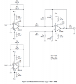
I would also be surprised if you were not sufficiently familiar with the answers to your questions with regards to either DAC I/V & filter example. But I did attach an example PCM1794 I/V and filter schematic for reference. Both the PCM1794 and ES9038Q2M are very widely known. (So I thought they were reasonable references without going into the details. Honestly an op-amp I/V or the following filter in a DAC are hardly that complex?)
My point (with those four examples) is that 1/4W 1% metal film resistors are sufficient for a number of reasonably demanding examples. If I am wrong please go ahead and explain.
Attachments
Last edited:
- Status
- Not open for further replies.
- Home
- Design & Build
- Parts
- Resistor Sound Quality Shootout