Simon,
Quoting you... "It turned out that it was not the change in resistance value but that he had changed from a metal film resistor to a carbon composition type. "
How is it that the SQ was so much better then?
And the comparable % distortion you cited in your calculations was so small as to be imperceptable, anyhooo.
20
He prefers the added high end from the distortion. What % distortion did I cite in my calculations?
Last edited:
Cap distortion?
-118dB second. How could anyone stand to be in the same room with that?
The name of the AP preset.
Compare it to the Carbon Composition distortion in post 37. They are different resistors and values, but the issues was does the source impedance reduce the distortion. It does a bit but not by the incorrect method you showed.
Now would you care to write the loop equation or do the Norton current equivalents?
Now the second harmonic is not thermal distortion, it also is not very easily perceived. But the higher orders are. If you add the minimum 15 dB boost for the spectrum of music at the low end, the important frequency band around 4,000 hertz with the distortions you are -105 almost perceptible by itself no other amplifier distortion required. Or just add a loudspeaker's 2nd harmonic distortion added to the resistors you will be around -95 in the band of interest. But the amplifier probably adds to that. Now add a few more signals than just a sine wave and the level rises even more. If you measure the amplifier I doubt you'll get better than -70 dB or .03% multi-tone distortion just from changing that resistor.
But of course you would never admit the OP actually was hearing a difference!
He prefers the added high end from the distortion. What % distortion did I cite in my calculations?
This...
.1% isn't perceptable. Not going to create an openness with lush odd harmonics.So allowing for masking sensitivity of 30 dB. F-M add of 16 db and 15 dB of music slope You should be able to perceive 5th harmonic distortion at a level of 61 dB below the music level. That comes out to .09% distortion just for the fifth harmonic distortion.
Now what the before modification distortion was and the after is really the only question.
20
But of course you would never admit the OP actually was hearing a difference!
At < -120dB? What he described? You're right, I don't. Neither do you, really, you're just enjoying kicking up dust around a trivial problem for reasons I don't understand.
The rationalization is comic.
SY,
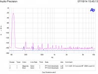
Just for you. Blue is the no signal baseline.
And the noise floor of the AP analyser is where, exactly...?
This...
.1% isn't perceptable. Not going to create an openness with lush odd harmonics.
20
.1% of what? Second harmonic isn't fifth and higher certainly are.
At < -120dB? What he described? You're right, I don't. Neither do you, really, you're just enjoying kicking up dust around a trivial problem for reasons I don't understand.
The rationalization is comic.
SY
Look at all the harmonics. Multiply that by any multitone input or following stage distortion and there will be hundreds of in phase garbage. Let me know when you do a loop equation or actual test.
If you have any actual basis state it.
Your comments unfortunately are not comic, just misinformed.
And the noise floor of the AP analyser is where, exactly...?
The lower blue line.
I did look at the harmonics. The insanely low harmonics.
Have fun with your dust. I suspect that your next kick will ignore the fundamental again. And I'll happily leave you to it.
Have fun with your dust. I suspect that your next kick will ignore the fundamental again. And I'll happily leave you to it.
At about 0.0002% THD that looks like the distortion of the AP itself, to me...-118dB second. How could anyone stand to be in the same room with that?
And the noise floor of the AP analyser is where, exactly...?
At about 0.0002% THD that looks like the distortion of the AP itself, to me...
The AP is at least -125 and there are techniques to extend that when needed. The simplest is averaging with dither.
SY
You really don't know what you are looking at.
When you have a device that generates harmonics almost up to light it is a problem. -118 on something simple like 2nd or 3rd ain't much. By 13th it is.
Let me know when you actually try anything real. Still waiting for your elephant, circuit equation or any measured results.
"A fanatic is one who can't change his mind and won't change the subject"
(Sir Winston Churchill)
(Sir Winston Churchill)
Under what conditions? I find that very hard to believe. The 2700 is their flagship model and doesn't claim to achieve that level of performance.The AP is at least -125
Under what conditions? I find that very hard to believe. The 2700 is their flagship model and doesn't claim to achieve that level of performance.
I did show the baseline.
You might want to look a bit at the concept of averaging FFTs to reduce noise. It takes a bit to do thousands of averages but it allows you to see a bit deeper. Then you can also narrow the bandwidth.
As to the signal generator it is easy to baseline it with a jumper cable to see the harmonic structure. The generator noise also averages out.
Not very hard to do. You might want to try an FFT that runs on a laptop wth an outboard A/D. Not very expensive and you can get decent results.
If I get the chance I'll do a metal film resistor with the same setup so you can see the difference. I did resistor measurements before and these results are consistent with those.
With a few tricks and good technique it is possible to look as deep as -160 re 1 volt.
Last edited:
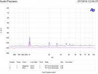
I did a quicky comparing a metal film 1/4 W to the 1/2 W carbon composition resistor.
I used 19 & 20 Khz for the IM source and so only needed 16 averages to see results.
As this is getting very tired I'll let this drop. I don't think SY will ever apologize to the OP for jumping on his question.
I used 19 & 20 Khz for the IM source and so only needed 16 averages to see results.
As this is getting very tired I'll let this drop. I don't think SY will ever apologize to the OP for jumping on his question.
Attachments
Simon7000,
Could you explain a bit more about the plots you have just posted? First of all, just so we can be sure, which plot goes with which resistor?
Maybe I'm misunderstanding something, but it seems to me that if you used 19 KHz and 20 KHz input signals, then all IM products would necessarily have to be at integer multiples of 1 KHz? And yet you seem to have clear peaks at about 2.7 KHz, which could not possibly be coming from the IM products of the two frequencies you used? Likewise, some of the higher ones too? Or is the labelling of the frequencies on the x-axis incorrect? Even the small peaks near to the vertical lines at 5 KHz and 8 KHz don't seem to tally with what one might expect. Could you say a bit more about what is going on?
Chris
- Status
- Not open for further replies.
- Home
- Amplifiers
- Tubes / Valves
- Resistor question