Did OP ever solder in the original stock resistor to see if it was just a bad connection? Seems pretty logical to me.
I was originally on board that a grid leak resistor value change might make a difference if the valve was gassy or defective. And of course at low frequencies due to the RC coupling (what is the value of the input cap?). But since going to the original 390k value yielded a sonic difference than well my money is an bad solder joint originally.
All this talk about the composition and or size/rating of the grid leak resistor making such an AUDIBLE difference is hard for me to swallow.
Last edited:
FFS, all we want is a diagram or at least a half decent explanation of the TEST SETUP. Otherwise all we see is just a couple of FFTs you could have cribbed from anywhere. A year's research? Don't make me laugh. It's a couple of distortion measurements on a couple of resistors (supposedly). 30 mins work, tops.
You didn't even say what volume of Linear Audio, or what thread. You think that's how academic 'research' works? Post pretty pictures and then (200 posts later) expect people to solve some kind of riddle about references? A school boy would do better.
Did you ask that? Or just comment?
Note that in the printed version the return symbol got changed to a ground and this was well noted by Samuel Groner.
Academic research needs to start with someone reading the article before commenting on it. I answer questions, did you ask any?
Attachments
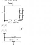
"Note that in the printed version the return symbol got changed to a ground and this was well noted by Samuel Groner."
Dang!, Of course, I knew that and just plain forgot!
This is Academic Research? Wow!
Dang!, Of course, I knew that and just plain forgot!
This is Academic Research? Wow!
Merlin, this was with 15mA roughly, or 15V across 1k, which Ed did (in his defense) state in the article. Not a particularly apt comparison, which is why he carefully didn't disclose that here. Par for the course. Oh, and LA Vol 1, since he didn't bother to cite.
Ed, since I posted the voltage divider equation (and you haven't bothered to do that basic step), I don't see why you're whining.
Ed, since I posted the voltage divider equation (and you haven't bothered to do that basic step), I don't see why you're whining.
SY. I am probably over-reacting. I do that.
But is it reasonable that one has to subscribe to and read external articles to be able to understand this thread? This is not what the OP posted.
But is it reasonable that one has to subscribe to and read external articles to be able to understand this thread? This is not what the OP posted.
But is it reasonable that one has to subscribe to and read external articles to be able to understand this thread? This is not what the OP posted.
Right, but the stuff Ed is kicking up is totally irrelevant to the OP's question and the subject of the discussion. So you don't really need the article. The out-of-context graphs can be ignored- if they were relevant, Ed would have specified test and measurement conditions to begin with.
Since voltage coefficient of resistance is specified for most resistors, you can just plug that in as the "delta" in the equations I gave and determine for yourself how much distortion will be caused by the resistor's nonlinearity.
Merlin, this was with 15mA roughly, or 15V across 1k, which Ed did (in his defense) state in the article. Not a particularly apt comparison, which is why he carefully didn't disclose that here. Par for the course. Oh, and LA Vol 1, since he didn't bother to cite.
Ed, since I posted the voltage divider equation (and you haven't bothered to do that basic step), I don't see why you're whining.
When I get to it I'll show you how to write the circuit equation and do the general case. You are skipping steps and that is hiding what is going on.
I am whining cause folks who aren't following are complaining rather than actually asking questions.
Now what voltage do you think is present across the 390K resistor in the actual system use? My guess would be around .1 VAC. So if we look at the resistor plot and weight it for that voltage and the maximum energy frequency (around 125-150 hertz) we really should be seeing the levels of distortion shown in the plot!
BTY the resistors under test were run at 1/4 of their wattage rating. Standard practice is not to exceed 1/2 of the room temperature wattage rating.
The real issue that is getting lost is the distortion of Carbon Composition resistors is not just thermal, it is fundamental to their construction. PTC and NTC resistors are also made from coal. Mixing the right dust was the method to minimize tempco. However the distortion pattern actually differs based on the source of the coal!
The audiophile favorites are usually the ones with the highest distortion. So I don't doubt the original poster can hear, just that what he is listening for may not be lowest distortion.
Why is there any surprise that higher resistance values have higher distortion? I just got some nice unused old stock 10 Mohm resistors, not surprising they have 30 times the distortion of the one I showed. Is that valid data from a few old samples? No, particularly since anyone using them is looking for distortion. (The third harmonic does not rise the same as the other orders.)
Now will you look up a Norton model and get the heads up on why a single resistor really can contribute that much distortion?
BTY the phrase "Voltage Coefficient" was used to class all the non-thermal distortion into one term. We can look at it better today and see more of the causes. For example in wirewound resistors at first it was the tempco of the wire, but as that improved it turned out you couldn't really get a good terminal connection to the resistance wire, so that is where the errors crept in. Voltage coefficient gets masked at higher voltages by the tempco errors. So it really isn't linear with voltage.
Last edited:
When I get to it I'll show you how to write the circuit equation and do the general case. You are skipping steps and that is hiding what is going on.
Nope, it's straightforward, simple, and correct. A basic algebraic equation. No steps skipped. Kicked up dust doesn't change that.
Yes, and add geometry of the resistor (diameter/length), way of "connecting" copper terminal with dust, method of aggregating dust and coal ... 🙄 carbon comp is an endless story ...However the distortion pattern actually differs based on the source of the coal!
After going back and checking that link, I think coresta may be really onto something! Has anyone else tried replacing the grid leak resistor with a 10Kg FM antenna? I'll bet it makes a huge diference, certainly more than the effects Ed is talking about. Unfortunately, I can't try it myself as I don't have any valve gear.🙁
You appear to be suggesting that a non-linear resistor acts by some mechanism other than resistance variation - perhaps a voltage source (generating the distortion) in series with the resitor value? If so, you still have a potential divider so the order-of-magnitude calculation from Jan still stands.simon7000 said:Not quite, if the resistor distorts the voltage across it, that is the voltage into the amplifier.
You appear to be suggesting that a non-linear resistor acts by some mechanism other than resistance variation - perhaps a voltage source (generating the distortion) in series with the resitor value? If so, you still have a potential divider so the order-of-magnitude calculation from Jan still stands.
No I am suggesting SY started the Thought Police parade and was wrong. Jan followed up on SY's assertion which also produced errors. And here you are adding to it.
The first issue is if the non-thermal distortion has the same impedance as the base resistor, an interesting issue, but totally unimportant here!
The volume control was mentioned as a 20Kb unit. Also mentioned is that it is placed interstage! 20K most folks understand to mean 20,000 ohms. "b" means a linear control!!! So since SY mentioned he didn't need to write the loop equation as his math was correct he clearly has magical powers to know what the circuit actually is. 🙂
One would normally load a 20K pot with a 2,000 ohm load if used as an audio potentiometer or it is used in a feedback loop where a linear pot also gives nice control action.
Now the OP asked why changing a resistor made what to him was such a large difference. The "Thought Police" (TP) here told him he was imagining things. It turned out that it was not the change in resistance value but that he had changed from a metal film resistor to a carbon composition type.
Now the TP also had problems with how weighting has to be added to distortion products to get a grip on perception levels and even ignored the fact that while uncorrelated signals add by the root of the squared sums distortion is often correlated so the errors add. So while the distortion added by the resistor may not by itself be entirely creating the change, it could be just enough added to put the complete unit's distortion into the clearly perceptible level.
So the TP pretty much so diss'd the OP. So of course I got called rude for diss'ing the uniformed contributors who offer their opinions rather than either look things up or even ask questions.
The final point being the OP asked a decent question about what he was hearing and the TP just have to opine without substance.
Still kicking up dust on a simple and clear issue. For the life of me, I can't figure out why you're trying to confuse this poor guy.
It doesn't matter what taper the control has, the worst case is a 10k source at -6dB. That's very basic electronics. Any other setting makes the "distortion" even lower, which is why everyone here who is trying to shed light on a clear and simple issue has termed the basic calculation "worst case." Basic voltage divider equation, again simple and correct.
It doesn't matter what taper the control has, the worst case is a 10k source at -6dB. That's very basic electronics. Any other setting makes the "distortion" even lower, which is why everyone here who is trying to shed light on a clear and simple issue has termed the basic calculation "worst case." Basic voltage divider equation, again simple and correct.
SY your magical powers may allow you to see the schematic. I don't have them.
Your are still assuming that the bias resistor is fed from a low source impedance and that the distortion mechanism is high impedance.
Perhaps you can share the schematic with us.
Your are still assuming that the bias resistor is fed from a low source impedance and that the distortion mechanism is high impedance.
Perhaps you can share the schematic with us.
The "Thought Police" (TP) here told him he was imagining things.
Good to see they can operate without me. Interesting though, .1V AC on 390K so you can extrapolate down to .026 micro-watts?
Good to see they can operate without me. Interesting though, .1V AC on 390K so you can extrapolate down to .026 micro-watts?
Late to the party as usual. Carbon Composition resistors have so much distortion the thermal doesn't even matter! (Also as you know the non-thermal distortion increases with resistor value.)
But then everyone here offers opinions only no measurements, no drawings etc.
Weren't you the one who used a particularly bad resistor as a noise source?
Late to the party as usual. Carbon Composition resistors have so much distortion the thermal doesn't even matter!
Simon,
Quoting you... "It turned out that it was not the change in resistance value but that he had changed from a metal film resistor to a carbon composition type. "
How is it that the SQ was so much better then?
And the comparable % distortion you cited in your calculations was so small as to be imperceptable, anyhooo.
20
- Status
- Not open for further replies.
- Home
- Amplifiers
- Tubes / Valves
- Resistor question