What seems also to work fine is the good time alignment made by DSP between the drivers...
People didn't saw that in Stereophile since the Dunlavys...
People didn't saw that in Stereophile since the Dunlavys...
Last edited:
I really like the D&D design and no doubt it is really well implemented and a super high performance speaker.
But I'm a little amazed they where able to obtain a patent on this .... isn't this the same concept Amphion has been using for many years? E.g. the Krypton3.
At least in the USA, getting a patent isn't too hard, but protecting it or having it be really valid might be. It often comes down to who has the best team of lawyers to intimidate the other side from going to court.
I really like the D&D design and no doubt it is really well implemented and a super high performance speaker.
But I'm a little amazed they where able to obtain a patent on this .... isn't this the same concept Amphion has been using for many years? E.g. the Krypton3.
registering a patent is not that hard to do. there are lots of patents about BS things (not in 8C case though!) people have. it's about differences. gradient speakers or cardioid speakers have old patents but 8C has new configuration (using waveguide on dome tweeter, rear subwoofers, etc...) that make it different from previous patents. if you come up with a new cardioid product you can also apply for a new patent.
What seems also to work fine is the good time alignment made by DSP between the drivers...
People didn't saw that in Stereophile since the Dunlavys...
sure thing! that would be child's play to get it done properly by using some impulsive response and time-aligning all drivers acoustic centers.
Electronic time-aligning only does a proper job on the measurement axis. And a good crossover design, passive or active, analog or digital, IIR or FIR, incorporates aligning by arranging amplitude and phase relations to a good sum signal. Again, only on axis though.
If you read the patent carefully you will see that it is only about the cardioid section and has nothing to do with any other aspects of the speaker. The point of difference to make it "unique" is targeting the midrange with the cardioid. More of this is made in the examiners comments in the original patent from the Netherlands.registering a patent is not that hard to do. there are lots of patents about BS things (not in 8C case though!) people have. it's about differences. gradient speakers or cardioid speakers have old patents but 8C has new configuration (using waveguide on dome tweeter, rear subwoofers, etc...) that make it different from previous patents. if you come up with a new cardioid product you can also apply for a new patent.
Make of that what you will, the speaker is very well designed regardless of any patent based fluff.
ME Geithain have been making speakers with a cardioid bass response for decades.
musikelectronic geithain gmbh - Home
They were not at all well known because when they started doing this they were in what used to be the German Democratic Republic.
As far as I know they also make their own drivers and electronics.
musikelectronic geithain gmbh - Home
They were not at all well known because when they started doing this they were in what used to be the German Democratic Republic.
As far as I know they also make their own drivers and electronics.
Electronic time-aligning only does a proper job on the measurement axis. And a good crossover design, passive or active, analog or digital, IIR or FIR, incorporates aligning by arranging amplitude and phase relations to a good sum signal. Again, only on axis though.
We have frequency response, phase response and drivers time-alignment. Am I missing something here?

The problem is that it isn't time-alignment, but space-alignment.
I don't get your point. I might be in a language barrier. could you please explain a little bit about this?
I'm thinking about building a special plane wave tube to use in measuring fibrous/porous materials' effect on the sound. the absorption coefficient thus the low pass filter effect and their effect on the speed of the sound. I'm thinking about a rectangular chamber with an eight-inch driver capable of 50hz - 1khz. has anybody any idea if this could be beneficial?
The problem is that it isn't time-alignment, but space-alignment.
Because it is a LR12 or LR24 and one want to avoid bad lobbing ? So acoustix center alignement (voice coils) instead of time alignment ( impulse response) ?
The crossover topology isn’t relevant but yes, you got it. Delay only helps on one axis. At 90 degrees the delay is gone and at 180 degrees it has turned the other way.
Last edited:
thanks
Thanks.
That delay related to the angle of listening position is not easy to understand if for instance two drivers have a flat power response untill 60% for illustration in their overlapp area and still in their pistonic behavior between on axis and +/- 60° listening position in that example.
Should we not, whatever the design, slope of the crossover, perform an impulse response measurment with a sweep tone around the frequency where the two drivers are planed to be crossed ? Then according the slope filter typology, adjust the gap to have a straight on lobbing on axis... then cross the fingers for what happen elsewhere ?
Sorry for the naive question, hope non too much off topic, but has the original poster, I have found the D&D 8C thread and Stereophile measurment quite inspiring but I suffer as a beginner at making a XO, clear process to do it whatever the book I read... there are formulas, but it's easy to mix up: time alignement, geometrical alignement of the acoustics centers, electrical phase then acoustic phase whatever the polarity changed and so on !
Typical example for me is whatever you do in a symetrical LR4 for instance, the upper driver on a same plan always will have 360° phase advance so will sound before the bottom driver. Not easy to find something that sumarize all of that in a single book and wiki 🙁
Anyway, thanks Marbakk for the inputt, I lurk and let the op to continue his thread .
.
Thanks.
That delay related to the angle of listening position is not easy to understand if for instance two drivers have a flat power response untill 60% for illustration in their overlapp area and still in their pistonic behavior between on axis and +/- 60° listening position in that example.
Should we not, whatever the design, slope of the crossover, perform an impulse response measurment with a sweep tone around the frequency where the two drivers are planed to be crossed ? Then according the slope filter typology, adjust the gap to have a straight on lobbing on axis... then cross the fingers for what happen elsewhere ?
Sorry for the naive question, hope non too much off topic, but has the original poster, I have found the D&D 8C thread and Stereophile measurment quite inspiring but I suffer as a beginner at making a XO, clear process to do it whatever the book I read... there are formulas, but it's easy to mix up: time alignement, geometrical alignement of the acoustics centers, electrical phase then acoustic phase whatever the polarity changed and so on !
Typical example for me is whatever you do in a symetrical LR4 for instance, the upper driver on a same plan always will have 360° phase advance so will sound before the bottom driver. Not easy to find something that sumarize all of that in a single book and wiki 🙁
Anyway, thanks Marbakk for the inputt, I lurk and let the op to continue his thread
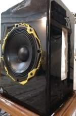
.We had a test cabinet lying around that is a good choice to start measuring for now. it's 40cmx27.5cmx24cm. It's a bass-reflex but I closed the ports with cardboard and hot melt glue. I routed the resistive ports/slots on both sides, they are 20cmx5.5cm. I'll start with Faital Pro 8PR200, for now, that will fit nicely on the enclosure. I added a thin layer of cotton fabric at the back of the driver to avoided any particle getting into the driver itself. I filled the cabinet with 30k/m3 density open cell foam and I'm getting 4-5dB of cancellation from 70-80hz up to 300-350hz at 180°. it seems the foam is not a good choice.
I have to measure front and rear responses individually and try to reach a pretty similar response on both sides by try and error and testing different resistive materials. it will take forever though.
I have to find a way to measure port response solely so I can find out how much time delay resistive material is adding in there.
Ohhh! I'm tired as if I haven't slept in a million years. it's 3 o'clock in the morning here and I'm typing around cardioid like there is no tomorrow.
Attachments
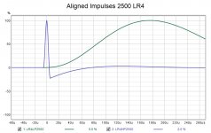
With a textbook minimum phase Linkwitz Riley Crossover the impulses need to be aligned at their starts not peaks, when this is right they will sum perfectly on that axis. There will be a power response dip from the crossover and other changes off axis from the directivity of the driver. In most cases aligning at the crossover point is the most sensible option. You don't have to be in the dark as to what happens but you will need to simulate with good polar measurements to see the effects on all off axis angles.Should we not, whatever the design, slope of the crossover, perform an impulse response measurment with a sweep tone around the frequency where the two drivers are planed to be crossed ? Then according the slope filter typology, adjust the gap to have a straight on lobbing on axis... then cross the fingers for what happen elsewhere ?
Try and plot it in Vituix or something similar that can do polar plots, 4-5dB of cancellation does not sound that bad as a start.I'm getting 4-5dB of cancellation from 70-80hz up to 300-350hz at 180°. it seems the foam is not a good choice.
I have to measure front and rear responses individually and try to reach a pretty similar response on both sides by try and error and testing different resistive materials. it will take forever though.
Attachments
Are you using this speaker in a house? If so, cardioid doesn't help you below 150Hz because you're below the room transition.
Our discussion has been about LF - below about 150 Hz. You are correct, in general, for typical locations of sources and listeners it makes no difference the source type - except for the need to EQ dipoles and cardiods. Your not likely to get much agreement on the frequency range that you mention.
I would tend to say that there would be some advantage to directivity in this frequency range, however, I have found that unworkable in practice. Of more importance to me is narrow controlled directivity above 1 kHz and a match of directivity at the crossover. The need for directivity control below 1 kHz IMO becomes ever less and less important. Its certainly not a bad thing so long as nothing important is given up to achieve it. I just haven't found it to be practical (read cost effective) to do that.
200-500Hz is better suited to cardioid.
I completely agree since a dipole has rear radiation that is of no use and can only cause problems. Cardiod is attractive in this frequency range and if I ever do a Magna Summa I might consider it.
Also, adjust your expectations based on where you measure your speakers.
Don't forget that the 20dB side cancelation was measured in a anechoic chamber. You are never going to measure that in a living room. 8 to 10dB in a living room is a pretty good achievement. Can you share the design?
- Home
- Loudspeakers
- Multi-Way
- Resistive port cardioid active speaker insipired by D&D 8C