I haven't played with CCS's before so I need some guidance so I can learn. I will try to attach a schematic.
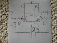
I would like to replace the 54.9K cathode resistor that is being shared by the 6SL7 with something better. I have 71 volts between ground and pins 3 and 6 of the 6sl7. I believe this will result in .0012932mA
Will this primative transistor,zenier and 2 resistor combination work or is there something better out there that will provide better results?
Attachments
You've got some volts to work with, so that's a good thing. Your scheme will work, but to make it optimal you want the Zener voltage to be fairly large so that the emitter resistor is also large- that increases the source impedance by roughly hfe times Re.
One neat trick is to tap the DC voltage feeding the reference off the plates of the diff amp through symmetrical resistors - that way, common-mode stuff is partially canceled.
I think you mean 1.29mA, not 0.00129mA.
One neat trick is to tap the DC voltage feeding the reference off the plates of the diff amp through symmetrical resistors - that way, common-mode stuff is partially canceled.
I think you mean 1.29mA, not 0.00129mA.
SY
Thank you for your reply.
Would the HV NPN CCS circuit work here? If so would it be better?
Yes, I meant 1.29mA
Thank you for your reply.
Would the HV NPN CCS circuit work here? If so would it be better?
Yes, I meant 1.29mA
Do you mean the cascode? If so, yes, but you can easily hit diminishing returns. If we take a single NPN with an hfe of 150, and we use a couple of LM329s in series as a reference, the emitter resistor will be about 13k. So the source impedance will be roughly (150)(13k) = 1.9M. Not bad, especially compared to the cathode impedance.
Are there any PCB available from anyone? I really would like to assemble something that looks neet instead of having a cluster farce of flying components.
SY,
Thanks for the response. I appreciate the fact that no one else would respond and you took the time.
SY,
Thanks for the response. I appreciate the fact that no one else would respond and you took the time.
Originally #5 posted by SY
If we take a single NPN with an hfe of 150, and we use a couple of LM329s in series as a reference, the emitter resistor will be about 13k. So the source impedance will be roughly (150)(13k) = 1.9M. Not bad ...
Sorry SY,
you should correct this one!

Kind regards,
Darius
oldeurope said:
Sorry SY,
you should correct this one!
Kind regards,
Darius
You're right, it's a bit higher than that since I neglected the 1/hoe term. But hfe time Re dominates.
Geek said:Anyone notice there's no DC return for the grids in that schematic?
It's a fragment. The grid is direct coupled from the plate of a voltage amplifier.
Wrong formula for the wrong component...
Hi SY,
you misunderstood me,
please note that a transistor and a triode are different components.
Don't treat them with the same formulas.
hfe and µ are different characteristics.
Think about it.
http://en.wikipedia.org/wiki/Bipolar_junction_transistor#h-parameter_model
Kind regards
Darius
Originally #9 posted by SY
But hfe time Re dominates.
Hi SY,
you misunderstood me,
please note that a transistor and a triode are different components.
Don't treat them with the same formulas.
hfe and µ are different characteristics.
Think about it.
http://en.wikipedia.org/wiki/Bipolar_junction_transistor#h-parameter_model
Kind regards
Darius
Re: Wrong formula for the wrong component...
As far as formulae go, to an extremely close approximation, the effective impedance of the constant current sink is:
hfe * Re
SY is correct. (actually it will probably be higher than this, since transistor tend to have a much higher hfe when operating at low collector current.
You are not making yourself clear, Darius.oldeurope said:
Hi SY,
you misunderstood me,
please note that a transistor and a triode are different components.
Don't treat them with the same formulas.
hfe and µ are different characteristics.
As far as formulae go, to an extremely close approximation, the effective impedance of the constant current sink is:
hfe * Re
SY is correct. (actually it will probably be higher than this, since transistor tend to have a much higher hfe when operating at low collector current.
That will certainly work. I have even used really puny constant current sinks like this: http://www.freewebs.com/valvewizard/ccs5.jpgburnedfingers said:
I would like to replace the 54.9K cathode resistor that is being shared by the 6SL7 with something better. I have 71 volts between ground and pins 3 and 6 of the 6sl7. I believe this will result in .0012932mA
and it still gives better balance than a 54k resistor!
Triode and BJT fundamentals
Hi Merlin, hi SY
this formula is totally wrong here.
For a triode the effective impedance of the "resistor multiplier" is approximately µ times cathode resistor.
Your formula describes the input resistance at the base of a bipolar transistor, hfe * Re = r(base).
I hope I made this clear for you. 🙂
Kind regards,
Darius
Originally #12 posted by Merlinb
You are not making yourself clear, Darius.
As far as formulae go, to an extremely close approximation, the effective impedance of the constant current sink is:
hfe * Re
SY is correct. (actually it will probably be higher than this, since transistor tend to have a much higher hfe when operating at low collector current.
Hi Merlin, hi SY
this formula is totally wrong here.
For a triode the effective impedance of the "resistor multiplier" is approximately µ times cathode resistor.
Your formula describes the input resistance at the base of a bipolar transistor, hfe * Re = r(base).
I hope I made this clear for you. 🙂
Kind regards,
Darius
Re: Triode and BJT fundamentals
Darius is correct.
The formula describes the base input impedance of a Bipolar Junction Transistor.
The collector output impedance of a transistor is very high, roughly a not perfect CCS.
Obviously this collector output impedance can be increased by emitter degeneration.
Think in a transistor CCS as a common emitter stage, with the base of the transistor connected to a stiff, invariable voltage source....
oldeurope said:
Your formula describes the input resistance at the base of a bipolar transistor, hfe * Re = r(base).
Darius is correct.
The formula describes the base input impedance of a Bipolar Junction Transistor.
The collector output impedance of a transistor is very high, roughly a not perfect CCS.
Obviously this collector output impedance can be increased by emitter degeneration.
Think in a transistor CCS as a common emitter stage, with the base of the transistor connected to a stiff, invariable voltage source....
Re: Re: Triode and BJT fundamentals
Thank you very much for the help, Jorge.
Kind regards,
Darius 🙂
Tube_Dude said:
Darius is correct.
The formula describes the input impedance of a Bipolar Junction Transistor.
...
Thank you very much for the help, Jorge.
Kind regards,
Darius 🙂
I typically use Cascode configuration for the CCS... Thats if you have the available headroom....
Chris
Chris
Tube Dude, you may wish to tell this to the writers of every textbook I have. They all show output (collector) impedance of a degenerated bipolar CCS as 1/hoe + Re(hfe), though some put in a factor of 2 to approximate the increase in hfe with lower current.
You can derive the expression yourself from first principles. You can assume that Re >> re for most practical values of Re. Since 1/hoe is generally << Re(hfe), the latter term dominates.
You can derive the expression yourself from first principles. You can assume that Re >> re for most practical values of Re. Since 1/hoe is generally << Re(hfe), the latter term dominates.
SY said:Tube Dude, you may wish to tell this to the writers of every textbook I have. They all show output (collector) impedance of a degenerated bipolar CCS as 1/hoe + Re(hfe), though some put in a factor of 2 to approximate the increase in hfe with lower current.
You can derive the expression yourself from first principles. You can assume that Re >> re for most practical values of Re. Since 1/hoe is generally << Re(hfe), the latter term dominates.
Good BJT designs do not rely on Hfe... And are not Hfe dependent nor temperature dependent..
In my job I have to design out the Hfe to a 3rd order term so it is not dominant...also, this basic circuit is a PTAT current source...so this can be compensated out to a fair degree....
If you want your Hfe high enough to not be a worry....then put in a Dalington configuration as the CCS ..... using an un-flitered divider to feed the base bias has it's advantage....allowing ripple to reject...
Chris
- Status
- Not open for further replies.
- Home
- Amplifiers
- Tubes / Valves
- Replacing a cathode resistor with a CCS