Thanks Steve.. I will check and have been checking the case to heatsink. Also I have been testing each transistor with my diode checker and all have been good thus far.. only have 6 in.. have some big problems with a database being flakey at work .
So I gotta ask, plead with someone to please check my logic in the past post and make sure I am substituting the right trani's.. I assume that the PNP is replaced with the PNP.. the reason I am concerned is the 2n's have the high # on the right side of the board and if my logic is right the ML's are backwards from that (the left has the 4's and the right the 3's).. there is a link to the data page a few posts ago.
On the locktite.. well; I've already done quite a few.. and I am checking the screw to nut for any loss and seeing none on my multimeter.. I guess I assumed that when you tightened the nut you were gonna have the threads connect and it would squish out the locktite in those areas.. locktite is am amazing product.. it will only cure in an oxygen deprived environment.. if you just pour some out and let it sit.. it will never cure. Trust me.. its all over one of my toolboxes.. 🙂
So.. I am guessing I should have just used some nail polish on the tip once it was snug. Maybe I will do that on the remaining 6 or maybe I will be a locktite guinea pig.. havent decided. And yes, blue of course.. red is great if you never want to remove it again without a torch.
Well.. back to work.. PLEASE SOMEONE.. just take a quick look at my above post asking for verification on the transistors.. I have looked at it 3 times and all I know to look for is pnp and npn.. hope I am right or I have lots of unsoldering to do...
joe
EDIT: here is my question
First question.. does the MJ15003 replace the 2n5878 and the MJ15004 replace the 2n5876?
I'll try and figure it out by looking at the specs.. but to be sure... if someone can verify I can start soldering.
Edit: Had them backwards.. the 2n5876 is pnp and the mj15004 is pnp.. so I fixed the above.. But still would like verification.
and here is the link
http://www.datasheetcatalog.com/datasheets_pdf/2/N/5/8/2N5876.shtml
barchetta said:does the MJ15003 replace the 2n5878 and the MJ15004 replace the 2n5876?
Short answer: yes.
/Hugo
Re: locktite
Hi Steve,
Locktite can have a high dielectric strength. If applied properly, most of the screw thread is left exposed. Therefore, no worries.
I'll say that I don't often use it this way, only where it's been factory assembled in that manner or when there is a history of the hardware loosening up. I use nail polish or a lacquer on the head normally (keeping clear of the tool opening).
Hi Joe,
Don't worry. Carry on as you were.
-Chris
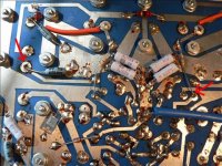
I just wanted everyone to see this before it possibly turned into a brown piece of toast.. 🙂
I just need to replace those two out put resistors that got toasted and then I can reassemble and start testing.
I just need to replace those two out put resistors that got toasted and then I can reassemble and start testing.
An externally hosted image should be here but it was not working when we last tested it.
An externally hosted image should be here but it was not working when we last tested it.
Nice job Joe!
Agreed a closeup of the solder side would be great so multiple eyes can take a gander.
Also, please do me a favor and double check to make sure you have all of the npn and pnp outputs in the right spots (compare to the other side).
Nice work!
Agreed a closeup of the solder side would be great so multiple eyes can take a gander.
Also, please do me a favor and double check to make sure you have all of the npn and pnp outputs in the right spots (compare to the other side).
Nice work!
I can't give you hi-res.. the website I use only gives the sizes you have seen.. I can email you them.. they are BIG.. I'll try and email Steve one after this..
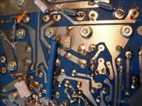
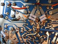
Here are some more I took closer..
Oh and all the transistors look right.. I have a photo from the original board and I used it. Ummm.. one thing though.. whats that transistor they all connect to?? I didnt replace that... It seems to test good though..
The schematic says VARO R0711xE Dual diode
Here are some more I took closer..
An externally hosted image should be here but it was not working when we last tested it.
An externally hosted image should be here but it was not working when we last tested it.
An externally hosted image should be here but it was not working when we last tested it.
An externally hosted image should be here but it was not working when we last tested it.
Oh and all the transistors look right.. I have a photo from the original board and I used it. Ummm.. one thing though.. whats that transistor they all connect to?? I didnt replace that... It seems to test good though..
The schematic says VARO R0711xE Dual diode
HOLY CRAP! I found what was going to be a dead short on a resistor lead I cut too long.. You can see it BARELY in the upper right of the top photo of the last post.. Steve should see it in the hi-res I sent him.. Damn.. I'm going over it again!
Boy, I'm I happy I made you take the pictures.
What more could be build in to delay the extinction? 🙂
Just kidding of course.
As for the transistor, no idea without schematic.
/Hugo
What more could be build in to delay the extinction? 🙂
Just kidding of course.
As for the transistor, no idea without schematic.
/Hugo
Hey guys,
I'm smiling at this end because I'd already emailed Joe most of what you've posted as I'm just now reading the thread... LOL!
Looks like we're all on the same page.
I've also asked him to add a bit more solder on the transistor pads and not to be afraid to hit them with some heat as we don't cold or fractured joints due to thermal cycling.
Please keep the comments / help coming...
Okay guys.. Thanks for all the input.. I bought this solder at Radio Hack.. and its got 4% silver.. but man.. its weird; all the joints look cold.. but I assure you; they are not.. compared to the factory (hmm this is so old, who knows maybe Mr. Pass Soldered a few of these! LOL)... they look really dull..
Steve caught the short too.. **** that woulda sucked...
Well; here is what I did.. I picked a lead of a transistor and used it for reference.. I read a 60v 90v and 110v on the "good" side.. and it read .10 .22 .36 and the new side read .10 .18 and .26 .. which of course means I got it up to 110v.. no DC on the output.
BUT something weird.. when I put my meter lead on the INPUT positive lead I start to hear "crackling" when I get to about 60v. I suppose I could do this on the good side and see what happens..
I have let it idle for 5 seconds at 110v.. no smoke; and no transistors I can reach get hot.. I have not the testis yet for longer than 5 seconds.. I wanted to hear what youguys thought about the weird crackling.. and if I remove the lead nothing...
Okay. I will go solder in the good side/ desolder the new side and see if it does the same thing.... be back in a bit..
Joe
Netlist said:Joe,
As you will rather want to be safe than sorry, I think you should isolate the long wires from the resistors as shown in the picture. A piece of shrink tube will get you a long way.
/Hugo
BTW.. I did not change out that resistor.. for some reason; I dont have those; I think (hope) I measured them and they were right.. so that is a factory install you are pointing to. I was going to order those and replace so I will do what you suggest when I get those..
Okay, I checked the other side and I do not hear the noise with the multimeter connected to the input.... Now this is weird... I am using a 2 ft aligator clip jumper to make this connection.. and its still there with only the lead connected!??? And you can see the lED's bounce slighly with it connected too.. so its like sound is being introduced into the input when the lead is on???
The noise is very quiet.. house has to be quiet for me to hear it and I am too afraid to turn it past 60v with that noise happening..
this is weird.. I will go tru just a RCA interconnect cable on it and see what happens..
EDIT: Okay with the interconnect cable on I hear nothing and I let it run for 10 seconds at full 110v input! No DC on the output the whole time.
Just had to go and buy fancy solder didn't ya????? Couldn't just have stayed with the normal stuff....
The "crackling" makes me nervous...
Since you have no dc at the output, I'm guessing that you might be hearing a 60 hz hum coming from the circuit itself. This is just a guess... I'm basing my guess on the fact that you have a test lead attached to the input terminal that is essentially not grounded.
Often you can hear the "music, tones, whatever" playing in a circuit if you listen closely and are driving it hard.
Apogee said:Just had to go and buy fancy solder didn't ya????? Couldn't just have stayed with the normal stuff....
The "crackling" makes me nervous...
Since you have no dc at the output, I'm guessing that you might be hearing a 60 hz hum coming from the circuit itself. This is just a guess... I'm basing my guess on the fact that you have a test lead attached to the input terminal that is essentially not grounded.
Often you can hear the "music, tones, whatever" playing in a circuit if you listen closely and are driving it hard.
What about bias at this point? I have not touched the pot.. I dont know how to set it other than the heat sink thing.. I think I have a document.. yes I do.. it tell you 1 ohm =194mv .68 oham =90v and .33 ohm =65mv...
Here is the rest.
1. all covers must be on
2. maximum allowable variation in temp from channel to channel is 5 degrees cetigrade
3. When using a .01 ohm resistor to measure bias current 10mv. =1a current..
I dont know what all this means?
Can I just hook my speaker up and see if it flys?
- Home
- Amplifiers
- Pass Labs
- Repair question re: threshold 400a