Don't feel bad K-amps. I like the Nak much better as well.
Don't have the manuals any more, but I'd love a copy of the scan. Do you have the CA-7 also?
I serviced them under warranty but could never afford one.
Everthing about this amp is BIG. Heatsinks, transformer, chassis. I could never get the type II or modded type I to go into limiting on a two ohm load. The 15A breaker (dedicated) always tripped first. For normal speakers, this amp will deliver obscene amounts of current.
-Chris
I remember having a SM for the PA-7 but I think I sold it along with the 2 PA-7's I had. I sold them after I needed cash as well has they would trip driving my ML CLS's... I guess they could not take any arcing abuse like the GFA-565's.
Beautiful amps man!
Beautiful amps man!
Hi Arif,
If they were the original PA-7's, there was a modification from Nakamichi to back off the protection circuit. You can tell if an amp is modified by looking at the amp PCB's. There will be a small daughter board mounted to each one with soldered solid leads. No more tripping.
I only had to repair one PA-7 or MK II. I found the remains of a copper box staple inside too. Nak paid me under warranty to do the repair. Darn!! Wasn't the amp's fault I don't think. They come wrapped in plastic in the box so you tell me ....
-Chris
If they were the original PA-7's, there was a modification from Nakamichi to back off the protection circuit. You can tell if an amp is modified by looking at the amp PCB's. There will be a small daughter board mounted to each one with soldered solid leads. No more tripping.
I only had to repair one PA-7 or MK II. I found the remains of a copper box staple inside too. Nak paid me under warranty to do the repair. Darn!!
Wasn't the amp's fault I don't think. They come wrapped in plastic in the box so you tell me ....-Chris
sorry for waking up
this old thread ....
i was wondering if possible to clone the nakamichi PA7 but operate it in normal class AB
does anybody think that this is possible ????
do you think that would be an easy thing to do ????
this old thread ....
i was wondering if possible to clone the nakamichi PA7 but operate it in normal class AB
does anybody think that this is possible ????
do you think that would be an easy thing to do ????
Hi Sakis,
Answered in an email, but I figured I should post my response as well.
Hmmm, I'm afraid I don't have it anymore. Darn!
Sakis, if you have a copy of my email to you, would you please edit it and post it here. Or, if you are unsure what should be posted, please send it back so I can put it up. I feel there is some information that would be useful. Not all of it of course.
In a nutshell, yes. This is possible by turning the bias current down. The circuit will not sound very good for reasons I don't wish to retype.
-Chris
For those still missing the service manual;
http://www.audio-circuit.dk/Schematics/Nakamichi-PA7-pwr-sm.pdf
http://www.audio-circuit.dk/Schematics/Nakamichi-PA7-pwr-sm.pdf
Hi Jan,
There was a modification to reduce the level where protection would come in. Would you happen to have that document? It involved the installation of two small PCBs soldered to the foil side of each amplifier PCB. It came complete with PCB diagram and schematic, so it could be reproduced should anyone need to do that.
Thank you very much for posting that service manual! I am trying to collect the manuals I no longer have. You have made me a little happier sir!
Best, Chris
Hello Chris,
I'm only glad to help 😉
Sadly I don't have documentation for these add-ons.
If someone has it, please upload it here or emaiol it to me, so I can put it into the Service Manual.
I'm only glad to help 😉
Sadly I don't have documentation for these add-ons.
If someone has it, please upload it here or emaiol it to me, so I can put it into the Service Manual.
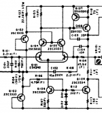
kilowattski said:Since it is a Nelson Pass design .....
Nakamichi P7 looks like having a voltage gain of ~20.
Thr input 2SK240 pair works 1mA each.
😕 Can not figure out the cascoding arangement ....
One 2SC3333 used as a backwards attached diode is connected to GND.
One 22k1 resistor feads the cascoding pair 2SC3333.
1. What will be the approximate VDS of this input excellent 2SK240 dual monolitic pair?
2. Is this Drain-Source voltage dependent of hoe much base current is supply to cascoding 2SC3333?
The input could very well be a Nelson Pass idea.
Probably it is 😎
Attachments
One 2SC3333 used as a backwards attached diode is connected to GND.
Is it being used as a 5 or 6V zener ?
Naah.
I can only think that the diagram of amplifier is not correctly drawn.
Maybe Nelson Pass could give us some clarifying, if he reads this.
I can only think that the diagram of amplifier is not correctly drawn.
Maybe Nelson Pass could give us some clarifying, if he reads this.
The thing is, there is another one biasing the diode string of the two current sources on the -ve rail. Someone makes the same mistake twice 😕 😕 , or is it a deliberate attempt to confuse us 
q102 acts like between 7v to 8 v zener.
1. so the 2sk240 jfets are at roughly 6v to 7v drain to source.
2. not to the first order
mlloyd1
1. so the 2sk240 jfets are at roughly 6v to 7v drain to source.
2. not to the first order
mlloyd1
lineup said:...
One 2SC3333 used as a backwards attached diode is connected to GND.
One 22k1 resistor feads the cascoding pair 2SC3333.
1. What will be the approximate VDS of this input excellent 2SK240 dual monolitic pair?
2. Is this Drain-Source voltage dependent of hoe much base current is supply to cascoding 2SC3333?
...
Hi ACD,
Well, at least you know the modification exists now. The PA-7II incorporated this change into it's design. That manual would be good to have as well.
-Chris
Well, at least you know the modification exists now. The PA-7II incorporated this change into it's design. That manual would be good to have as well.
-Chris
not a mistake or confusion
😉
that one helps reduce impacts of negative rail voltage modulation on the current in the diodes (which contribute to the reference voltage for constant current sinks).
hmmm ... i suppose that was a very long-winded way of saying it improves the negative power supply rejection ratio.
😀
mlloyd1
😉
that one helps reduce impacts of negative rail voltage modulation on the current in the diodes (which contribute to the reference voltage for constant current sinks).
hmmm ... i suppose that was a very long-winded way of saying it improves the negative power supply rejection ratio.
😀
mlloyd1
DRC said:The thing is, there is another one biasing the diode string of the two current sources on the -ve rail. Someone makes the same mistake twice 😕 😕 , or is it a deliberate attempt to confuse us
- Status
- Not open for further replies.
- Home
- Amplifiers
- Solid State
- Renovating a Nakamichi PA7