Hi,
a preferable way to provide a highly desirable clean voltage to the bases of the cascoding transistors could be the combination of high impedance current source and low impedance voltage reference.
This application does not reject anything.
a preferable way to provide a highly desirable clean voltage to the bases of the cascoding transistors could be the combination of high impedance current source and low impedance voltage reference.
This application does not reject anything.
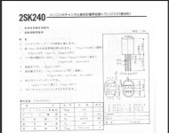
It`s not monolithic, just matched pair, not more exciting than 2x2SK170 (but not less excellent either).1. What will be the approximate VDS of this input excellent 2SK240 dual monolitic pair?
Lumba,
A 2SK240 is in fact two 2SK170 bonded in a aluminium shell.
What is wrong with a zener and resistor method to bias a cascode?
Possibly Mr. Pass do not know how make it better...javascript:smilie(' ')
')
A 2SK240 is in fact two 2SK170 bonded in a aluminium shell.
What is wrong with a zener and resistor method to bias a cascode?
Possibly Mr. Pass do not know how make it better...javascript:smilie('
')Hi m2003br,
I have seen these go noisy in some cases, which is why I have some left over.
-Chris
I still have a couple 2SK240s. They are two transistors tightly bonded together, TO-92 case style in an aluminum casing. I wouldn't be surprised if these were a pair of 2SK170 transistors, but I'm not about to crack one open to look.A 2SK240 is in fact two 2SK170 bonded in a aluminium shell.
I have seen these go noisy in some cases, which is why I have some left over.
-Chris
m2003br,
That`s exactly what I said.A 2SK240 is in fact two 2SK170 bonded in a aluminium shell.
If you want to supply nasty noise, use zeners.What is wrong with a zener and resistor method to bias a cascode?
Working on a Nak Pa 7A II
We increased the cap size to 47K. Replaced all small caps and controls. It seems to be AC coupled and neither pot is for the offset. Power up Ok, but I think we had bias runaway during testing and it appears the 2.2 ohm in the turn on protection circuit acted like a fuse. A has anyone seen this? It is under the front plate on a PCB. I just need to determine if it is a 2.2Ohm or 2.2K It is a Noble and says 2.2ohmK on the side.
We increased the cap size to 47K. Replaced all small caps and controls. It seems to be AC coupled and neither pot is for the offset. Power up Ok, but I think we had bias runaway during testing and it appears the 2.2 ohm in the turn on protection circuit acted like a fuse. A has anyone seen this? It is under the front plate on a PCB. I just need to determine if it is a 2.2Ohm or 2.2K It is a Noble and says 2.2ohmK on the side.
Dear VintageAmp,
Search for your free service manual in eserviceinfo.com
The resistor for the soft start is 2,2 Ohms 20W (the "K" letter stands for 10% tolerance).
Ensure that the Bias trimpot is at maximum resistance before power on.
You should check if the soft start relay is operating, if not, the next resistor will burn too.
Thank you, I found a schematic and indeed a 2.2 ohm was used. I installed a 1.5 ohm 50 W Dale. The unit is again working. Now to fine tune the bias. What does VR12 do? It is not on the schematic I have for the Mark II which is AC coupled.
In the older model (not MKII) VR101 is for adjustment of Output DC Offset and VR102 for BIAS.
My schematics for PA7-II show only the Bias trimpot, VR11.
I think VR12 is for DC offset, maybe implemented later in production.
Just check if it is connected to (or instead of) R118 and R119.
My schematics for PA7-II show only the Bias trimpot, VR11.
I think VR12 is for DC offset, maybe implemented later in production.
Just check if it is connected to (or instead of) R118 and R119.
Repair Conclusion
I have found in another thread the PA 5 diagram that resembles this model. On the PA 5 it says 3.9V I am measuring 4.4 on the Right and 5.3 V on the left after replacing the control pots. It appears to be a front end bias adjustment. I think I'll adjust for 4.5V
After replacing the FETs several times I discovered a cold/broken solder joint on a current source. It pays to re-solder many of the connections on the PCB if removed. 🙂
- Status
- Not open for further replies.
- Home
- Amplifiers
- Solid State
- Renovating a Nakamichi PA7