I'm using tinted acrylic. It's pretty dark so white portion of display board is not that obvious. The acylic comes with protective paper, so I could cut out the window just for the display size (but I didn't). The blue lettering is a bit dark (even with max brightness applied, I wonder if there is a way to increase it?).
Also, when you mount the knobs directly to plastic shafts on encoders, the feel is not 'high end' (the nobs are a bit 'loose' also). It would be better to use metal shaft extenders and mount the encoders further away from display, with some additional damping applied to rotation of the shafts for more solid 'feel'. This would be definitely recommended.
But I'm greatly impressed with programing options on board.
It would maybe be easier to use an encoder with metal shaft, I am not sure if grayhill makes an identical one, with the 1" knob the feel is not too bad. I won't be using the knobs much, the point of the whole thing was to use the remote. 😉
By the way, does the remote work throught the blue window?
I started to wonder about the blue plastic acting as a filter for the remote ir frequency after I was done.
By the way, does the remote work throught the blue window?
I started to wonder about the blue plastic acting as a filter for the remote ir frequency after I was done.
Hi Peter & grataku,
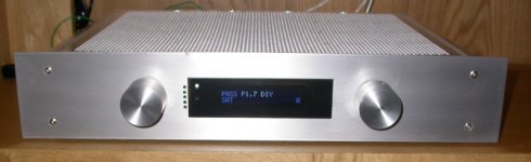
below should be a picture of my P1.7 with the APOX kit. The window is a 'frosted' (clear) acrylic, approx 2mm thick. I masked the area for the APOX display and for the 'blue' stand-by LED / IR receiver diode and spraypainted the backside black. After peeling the masks of, I mounted the acrylic with two thin strips of double adhesive tape to the front.
At this point in time the front is an interim solution - the final one will be milled and the two knobs somewhat 'sunk-in'.
Regards, Andreas
Attachments
grataku and Peter,
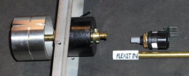
Grayhill does not seem to make an easily substitutable controller with a metal shaft. So, I switched the controllers to a Tosoku-CUI Stack; part number is RE21NC25C20RA. The Digikey number is 102-1019-ND and are $48 apiece.
The shaft is 20mm long and metal, so it is more robust. It is 6 mm in diameter so fits large, heavy knobs. The clicks are quieter and feels 'high-end' and also has a switch feature.
It comes with flying leads (5 of them; there are 6 pins on the Greenhill encoder, but 2 of these are for ground and are simply shorted together on the IR1 board). This new controller is a direct fit, but the leads need connecting in reverse order: leads 1 to 5 on the new controller go to holes 6 to 2 on the IR1 board (the two ground pins 1,2 are shorted on IR1).
The only problem I have with this new controller is that the output changes very rapidly as the rate of read-out is different than the Grayhill units. Perhaps through software, Dale can allow us to adjust the rates of read-out from the encoders?
Regards, Robert
Has anybody been able to contact Craig or Dale? Thier home page is down and I cannot download upgrades from the Apox page.
Anthony
Anthony
I have no idea of what's up with these two. They might have retired in a villa in the south of france 😉
grataku said:
By the way, does the remote work throught the blue window?
I started to wonder about the blue plastic acting as a filter for the remote ir frequency after I was done.
It shouldn't be a problem. I used that sort of windows before and remote worked fine.
I did some selective damping on chassis panels, and decoders make less noisy clicking now. But to have the 'feel' of Mark Levinson preamp, much more modification is required.
Here's my idea for the next version. I will use a fly wheel from old tuner. This adds rotational mass and you can spin the knob for faster movement (on its own). The flyweel comes with metal shaft already, so I only use 1/4" bronze fitting in front panel. The other end will be connected by flexible tube (plumbing) with the encoder. This allows to use any encoder, but the 'feel' should be substantially improved (read more solid, like a Swiss watch and not plastic timex😉). Also, I think that incoder has to be coupled to a heavy structure to make the clicking less noisy.
Attachments
Peter how is the performance
Peter,
How good is the performance of this volume control, is the rise time as quick as fast as regular conductive plastic pot. I was thinking that it would have more stray capciatance do to the layout, have you listen to it yet. Does the PCB have a dry film solder mask.
You chassis looks very nice again.
I didn't try it yet. But I presume it's not as fast as plastic pot. It takes more rotation to increase the volume. The board seems to have very compact design and solder mask.
http://www.dipchipelec.com/APOX4/apox-shm.jpg
http://www.dipchipelec.com/APOX4/apox-shm.jpg
Performance
Peter,
When you get it running, please let us know how it sound compared to your experiences with other volume controls.
The reason I asked about the mask is I have had some bad experiences with wet film mask and contamination. The wet film mask can have more stray capacitance than the dry film.
Thanks
I have no idea of what's up with these two. They might have retired in a villa in the south of france
Actually the truth is, I got laid off last week, and have been trying desperately to find a job.

I wish I was in a nice little villa.
Sorry for the absence!
-Craig Beiferman
Sorry to hear that Craig, I hope you find something soon. What is it you do in your professional life?
BTW - Were you aware your site is not working properly?
Regards
Anthony
BTW - Were you aware your site is not working properly?
Regards
Anthony
HI TECH SUCKs NOW
Craig,
It has reached epidemic proportion for engineers in Dallas TX. If your in communications it's bad news.
Good Luck
Craig,
It has reached epidemic proportion for engineers in Dallas TX. If your in communications it's bad news.
Good Luck
Good luck, let me know if I can assist you in any way, Craig! You have my email address, please contact me privately.
Petter
Petter
dipchip said:
Actually the truth is, I got laid off last week, and have been trying desperately to find a job.
I wish I was in a nice little villa.
Sorry for the absence!
-Craig Beiferman
Sorry for making a joke, awhile ago Dale told me the situation was bad, I didn't know it was THAT bad.
The only things that seems to be happening big time around Boston are construction and the big biotech/pharmaceutical moving in. With the bedazzling costs of real estate around MIT they must REALLY want to be here.
Hi Dipchip guys,
Are you still in operation enough to send out boards and projects that you have in stock? If so, what is available?
I'll bet some people have been meaning to order but need a reminder.
Are you still in operation enough to send out boards and projects that you have in stock? If so, what is available?
I'll bet some people have been meaning to order but need a reminder.
Hi Everyone,
Yes, we have some stock left.
We also owe some software updates. With the layoff, I have been spending all of my time on a couple of contract jobs and sending out resumes (also selling misc...). I hope to remedy the situation soon. I now have three interviews scheduled for this week.
Wish me luck....
Best Regards,
Dale
P.S. Thanks!
Dale and Craig,
I'm very sorry to hear about your personal problems. My prayers are with you both.
On the issue of parts, I need to get at least 4 more IS1 boards and 1 more IR1.
Regards, Robert
I'm very sorry to hear about your personal problems. My prayers are with you both.
On the issue of parts, I need to get at least 4 more IS1 boards and 1 more IR1.
Regards, Robert
Apox Problems
Hello guys,
this is a message for all the diyaudio community especially for Craig and Dale.
Day 18/10/2003 I posted to Craig and day 21/10/2003 to Dale the following message:
“Craig,
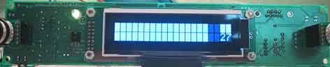
last week I have received the apx boards, they are assembled now but I have some problems.
when you switch on the boards APOX-IR1, and APOX-API the display look like the photo below.
The apox-ir1 recognize the apox-api when you turn the right or the left encoder the led on the apox-api flash but main part of the display stay on there is no way to see any words what you can see moving is just volume numbers. Same thing when the apox-api is not connected except that when you turn the volume encoder numbers stay on zero.
Second strange thing when you turn the volume encoder quickly the logic of the board does not follow the rotation of the encoder. For ex. lets say you start from 20 turn quick clock wise the encoder then when you stop turning you can see on the display 0 or 15 or whatever number. When you turn the encoder slowly the numbers on the display follow the rotation of the encoder
I have checked and rechecked all the connection an components position the whole assembly process was done following the assembly instruction that I have found on the dipchipelec web-site, every thing is where it should be. The PIC was managed carefully using electrostatic control procedures.
I have to say you that when I have received the display there was no protective plastic on it and there were same scratches on it.
Why this? what you think about?
Waiting for your answer, regards
Antonio “
Today one week after no answer at all.
What I have to think?
This two guys just sell the boards with no assistance?
I know that Crag has some problems to find a new job, but is not correct to not answer to message like the one above.
The reasons why the apox board don’t work could be many: my wrong assembly, a wrong PIC programming, a broken display.
I know you ( Craig and Dale) are gentlemen, you can answer to my message so we can work to fix the problem.
Regards,
Antonio
Hello guys,
this is a message for all the diyaudio community especially for Craig and Dale.
Day 18/10/2003 I posted to Craig and day 21/10/2003 to Dale the following message:
“Craig,
last week I have received the apx boards, they are assembled now but I have some problems.
when you switch on the boards APOX-IR1, and APOX-API the display look like the photo below.
The apox-ir1 recognize the apox-api when you turn the right or the left encoder the led on the apox-api flash but main part of the display stay on there is no way to see any words what you can see moving is just volume numbers. Same thing when the apox-api is not connected except that when you turn the volume encoder numbers stay on zero.
Second strange thing when you turn the volume encoder quickly the logic of the board does not follow the rotation of the encoder. For ex. lets say you start from 20 turn quick clock wise the encoder then when you stop turning you can see on the display 0 or 15 or whatever number. When you turn the encoder slowly the numbers on the display follow the rotation of the encoder
I have checked and rechecked all the connection an components position the whole assembly process was done following the assembly instruction that I have found on the dipchipelec web-site, every thing is where it should be. The PIC was managed carefully using electrostatic control procedures.
I have to say you that when I have received the display there was no protective plastic on it and there were same scratches on it.
Why this? what you think about?
Waiting for your answer, regards
Antonio “
Today one week after no answer at all.
What I have to think?
This two guys just sell the boards with no assistance?
I know that Crag has some problems to find a new job, but is not correct to not answer to message like the one above.
The reasons why the apox board don’t work could be many: my wrong assembly, a wrong PIC programming, a broken display.
I know you ( Craig and Dale) are gentlemen, you can answer to my message so we can work to fix the problem.
Regards,
Antonio
- Status
- Not open for further replies.