One thing I noticed with a spreadsheet, is that when I choose 40k for largest series resistor and 50k for argest shunt resistor, the table shows 180k as maximum input resistance. But how is it possible?
It seems like following settings might work well for me:
Series resistors 40k, 25k and 7k. Maximum shunt resistor: 40k. Will try to build it and see how it performs. I will probably have more questions later😉
Series resistors 40k, 25k and 7k. Maximum shunt resistor: 40k. Will try to build it and see how it performs. I will probably have more questions later😉
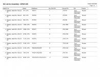
Dale, there are several errors in the 5K impednace kit you sent out in respect to duplicate component labels. I do not have the sheet in front of me but they are easily spotted. I assumed all the relay resistors were to be symmetrical 12 resistors in all 3 per input relay. I referred to the schematic on the two relays that had proper resistor placement documentation and electrically duplicated the other two.
Could you look at the supplied sheet again and just verify the component placement of the 4 effected resistors?
BTW - Did you say my earlier post that got buried by your conversation with Peter? 🙂
Regards
Anthony
Could you look at the supplied sheet again and just verify the component placement of the 4 effected resistors?
BTW - Did you say my earlier post that got buried by your conversation with Peter? 🙂
Regards
Anthony
Peter Daniel said:One thing I noticed with a spreadsheet, is that when I choose 40k for largest series resistor and 50k for argest shunt resistor, the table shows 180k as maximum input resistance. But how is it possible?
I see it now. The impedances are given for a balanced circuit and not single ended
Thanks Dale, I will verify I have the correct placements.
How are you and Craig doing? Is DipChip going to get back in the game anytime soon? I know you have been on the side lines for personal reasons for a while. I hope you guys can pull your lives back together soon, I hit a rough patch myself about ten or so years ago. I was out of work for 16 months!
Regards
Anthony
Hi Anthony,
Thanks for the kind words.
Actually, I start a new job on Monday at Sun Microsystems as a software manager in the Solaris Network protocols group.
Craig and I would both like to start developing some new products soon!!!
Craig may actually be thinking of trying to do this full time. Of course, the audio (APOX) stuff will need to be supplemented with our industrial control products.
Best Regards,
Dale
If you start developing some Robotic interfaces and control products drop me an email. I am the purchaser at a Pharmaceutical research company and we do a lot of Robotic protoyping.
Regards
Anthony
Regards
Anthony
Hi Anthony,
We already do!!!
1) We have a USB-CAN interface board to talk to our
2) CAN based motion controllers.
These are great for small robotic systems.
One motor controller board is only 3.5"x1.5" with a 5A discrete H-Bridge driver.
Best Regards,
Dale
We already do!!!
1) We have a USB-CAN interface board to talk to our
2) CAN based motion controllers.
These are great for small robotic systems.
One motor controller board is only 3.5"x1.5" with a 5A discrete H-Bridge driver.
Best Regards,
Dale
When you get you homepage back up and running I will forward them the link. Do you have a direct link for the HTML pages?
Regards
Anthony
Regards
Anthony
It seems like choosing proper bypass resistors is quite important.
In my test circuit the max shunt res. is 25k. The bypass resistors are as follows: 50k, 25k, 7.5k. The volume doesn't change smoothly. I have let's say values -11dB, -10db, -12dB, -11dB, -13dB (in that order).
However, when bypass resistors are equal 50k, 7k5, 4k, the volume changes correctly.
This brings the issue what is the mechanism behind choosing those resistors as obviously they can't be picked randomly.
I'm using real time simulation, with generator and dB meter.
Hi Peter,
You are correct. Craig wrote some C++ software to optimize the volume settings based on our resistors. The software made choices based on maintaining a log curve and making sure that the lowest impedence values for a given setting were used.
Craig would have to use your specific values and generate a new lookup table. We would have to supply you with new microcontrollers for the SHM board with custom firmware.
Best Regards,
Dale
Hi Dale,
Here's my impressions. The circuit and software works great if you want to use it at the output and concentrate on lowest impedance. In this case resistance fluctuations between 2K and 4K are not really important. But even in my correctly working circuit I noticed that although the values were usually around 500ohm and 1k5 (output resistance) at approx 10 maximum positions the output resistance was 50k (which seems to be high for the output).
Also, I noticed that circuit is changing resistance substantially with some subsequent steps. It means that output resistance goes up and down (let's say 5k and 10K interchanging for -11 and -11.5dB and again -12dB for instance). It may be fine for keeping nicely defined steps, but in reality and from Audiphile POV, accurate 0.1 or 0.3 steps are not that important rather than keeping steady resistance and similar values in certain range of volume settings. I also believe that 2 resistors in parallel and 3 resistors in parallel sound different and if system goes constantly from 2 to 3 resitors in parallel with every click of the knob it will be noticed subjectively.
Now, it seems that the circuit is optimised for preamp's output location. But what if somebody wants to use it in front of the amp, without using preamp? Playing with GC, it seems like a best solution and some people simply refuse to use preamps. From GC threads, one might also speculate that those amps reached similar popularity as the Alephs (at least in diy circles). So the dipchip module might be a good candidate for passive pre stage, mounted directly at the amp and in such way that the problems with passive preamps are gone (input impedance on the higher side when directly at the amp). And this is possible since long control cables allow the control unit to be at the source and the apox volume modules in the amp.
Talking about the proper resistor values for such setup, I would see it somewhat like that: The minimum input impedance should be aprox 20k and it shouldn't go higher than 50k.
The combined bypass (series resistor values) should have 3 values, corresponding to log pot operation. It could be for instance 10k, 25k and 40k. Now this values could be achieved with 3 series resistors, but never more than 2 resistors in parallel. Also those values stay put in operating range and thay don't change when you go from -12dB to -13dB. I mean 10K stays permanent in 1/3rd of operating range (let's say from 0dB to -6dB), after that 25K value is engadged (from -6dB to -12dB) and eventually 40k (from -12dB to -50dB). In all those 3 ranges the shunt resistors perform their logic to keep appropriate steps possible. It is only a rough speculation and it may work better with different values applied.
Another thing I would rather see is not steps marked 0-255 as this doesn't say really nothing and is only convenient when people want different resistor values and play with them. But keeping the display in real dB steps would be much nicer and more useful. In this case you would have to choose a fix resistance choices, as I already found out that playing with values doesn't bring expected (by me) results. So it should be either something to use at the output (like 5k max, for instance) and something to use at the input of SS amp (20-50k max) and maybe something to use in tube equipment if there is enough interest.
I understand that you also offer fixed resistance board, but it's limited to 24 positions only and not everybody wants to have 20 reistors in series at the input.
I still believe that good series-shunt control is possible, but with current software option I don't think it can be used at the amp's input. I also understand that it wasn't designed with this in mind and I didn't buy it for that reason. But it would be nice to have something more flexible available as well. This is a great, expandable system and I'm not trying to complain, but rather present more useful input.
Now, how many people actually build it already?😉
harvardian said:Hi Peter,
You are correct. Craig wrote some C++ software to optimize the volume settings based on our resistors. The software made choices based on maintaining a log curve and making sure that the lowest impedence values for a given setting were used.
Craig would have to use your specific values and generate a new lookup table. We would have to supply you with new microcontrollers for the SHM board with custom firmware.
That is what I found when playing with the notebook, it looked like it needed to be more a little more complicated (or alot simpler). But not knowing what the firmware was I found no way to do it right.
The idea is really good but do you really need 8bit resolution for volume control? With new software there won't be many combinations given target impedances, in order to get the ladder right.
I have a detented pot on my current preamp that allows for maybe 30 different setting I probably use a grand total of 4 settings.
Dale,
congratulations on your new job.
grataku said:
I have a detented pot on my current preamp that allows for maybe 30 different setting I probably use a grand total of 4 settings.
That's exactly the case in my setup as well. I would prefer less positionns (let's say max 60, with 1 dB intervals) than 255, done in such way that audio performance may be suffering.
I already set the volume step to 10 in my setup, because otherwise I would have to do too many turns to set the desired level😉
Hi Peter,
I have impressed upon Craig the importance of making you happy. If you can live with less values and less than perfect intervals, than we can probably come up with some better options for you.
Could you send me an email that puts all of your requirements into one coherent statement.
Minimum impedence, max
minimum number of volume steps you could live with.
etc...
Best Regards,
Dale
Mail to
support@dipchipelec.com
so that both of us get a copy
Peter Daniel said:
I already set the volume step to 10 in my setup, because otherwise I would have to do too many turns to set the wanted volume😉
Considering that spinal tap had 11 notches 255 seem excessive. 😉
harvardian said:Could you send me an email that puts all of your requirements into one coherent statement.
I will do it.
I also hope that I'm not causing too much trouble, but as a serious 'audiophile' 😉, I always concentrate on more useful and practical features as I already had my fun with toys in a past😉. If this works good, I might be ordering more in a future as well. Especially, I'm thinking if this could better S&B transformers. I think it might, and finding recently that non inverted GC plays quite good, a passive, resistor based volume control, became much more appealing too. It was not possible with inverted GC as it would change the gain of the amp.
Thanks.
Peter Daniel said:
That's exactly the case in my setup as well. I would prefer less positionns (let's say max 60, with 1 dB intervals) than 255, done in such way that audio performance may be suffering.
I already set the volume step to 10 in my setup, because otherwise I would have to do too many turns to set the desired level😉
Why 1 db intervals Peter? The human ear cannot discern changes in volume less than 3 db. That would mean only 18 setings on a 60 db curve!
Regards
Anthony
- Status
- Not open for further replies.