Petter,
I have never been a big fan of combining the digital gnd with the audio gnd, at this point I don't get what the fuzz is about with floating digital 5v. I am going to use a fully fledged regulated PS using LT1085s, no "wall warts" for this baby.
I spent $400 on this setup I am not going to skimp on the 5V.
RLJones,
for future reference it would be helpful for everybody not to freak out if and when a problem arises. I know it can be frustrating but it doesn't help anybody to launch accusations left and right, especially with people that stand behind their products.
See fuzzbrain01 post under:
http://www.diyaudio.com/forums/showthread.php?s=&postid=216706#post216706
Same experience here, most of the time is operator error, oversight, or a problem that can be trivially corrected.
grataku,
agreed.
as for the 5v supply, my steady state requirements are almost 2A and i kept having a slight droop to about 4.8V (dispite several different regulators, etc) and this led to erratic behavior of the IR1 and other boards. by chaning to a switching supply, rated at 2.8A, the digital supply stays at 5.15V and no more erratic behavior.
craig,
this is a very good s/n ratio; it is unweighed too. the distortion figure is quite good too, especially considering that it is at 10kHz and a fully discrete gain stage (6 transistors total). at 1kHz it is still around 0.007% THD.
***
academic discussion:
the one thing that still doesn't make sense: even assuming that the digital supply was contaminating the signal (image 3), how does it feed into the SHM when the signal is going through the SHM? All boards are active in image 4 and working away, yet when the SHM is added into the signal path in image 5, the distortions increased. logically, they should stay the same unless there is some sort of coupling going on between the digital portion and the analog portion on the SHM. why does this happen?
regards, robert
the G-job of legends
Here is my first episode to the miniseries dedicated to my remote control preamp based on the excellent dip-chip kit.
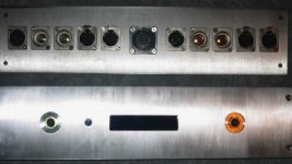
This episode covers the front and back panels. The former was by far the most complicated part of the design.
This took a long time to design with autocad and even longer to machine, as the title implies, under the strenuous G-job conditions of clandestinity narrow machining time-windows _AND_ last, but not least, and Al supplier that doesn't understand the difference between plate and flat bar and his own set tolerances for ordering cuts.
All in all I am extremely happy with the results.
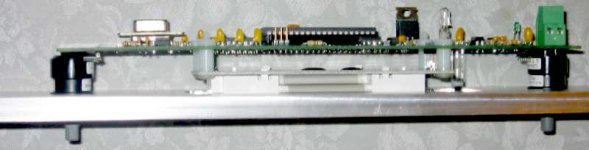
The front panel is 3/8 thick, back and sides (not shown, yet) 1/4 in, top and bottom is 1/8.
Details:
the encoder hole on the panel had to be countersunk both on front and back 1" and 3/4", respectively. This was done to allow the fastening of the encoder to the panel and to allow the button action on the encoder to happen without the unsightly knob sticking out from the front panel. The knob now will sit a hair below the panel level for optimal looks
The narrow LCD window was cut from the front and a much larger and deeper recess was carved out of the back to accomodate the IR sensor and a piece of very cool electric blue piece of acrylic.
Of course the picture shows neither the beauty of the acrylic nor the intricacy of the design 😉 D: that's because I couldn't resist mounting all the parts to the panel. By the way, the orange hue is only in the picture.
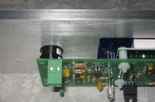
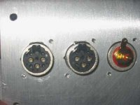
Back panel was machined for Neutrik connectors, as you can see XLR require extra work to accomodate the complex profile. The preamp will have a separate PS Humpty DUMPty and will be connected using the black shell connector in the center.
One caviat of using english screws to fasten swiss XLRs is that the right screw is a #5-40 flat head. As Goldilocks said: 6-32 is too big and a 4-40 is too small... 🙂
later,
PS the pictures are actually worse than I thought, the connectors don't even look straight, but they are!
Here is my first episode to the miniseries dedicated to my remote control preamp based on the excellent dip-chip kit.
This episode covers the front and back panels. The former was by far the most complicated part of the design.
This took a long time to design with autocad and even longer to machine, as the title implies, under the strenuous G-job conditions of clandestinity narrow machining time-windows _AND_ last, but not least, and Al supplier that doesn't understand the difference between plate and flat bar and his own set tolerances for ordering cuts.
All in all I am extremely happy with the results.
The front panel is 3/8 thick, back and sides (not shown, yet) 1/4 in, top and bottom is 1/8.
Details:
the encoder hole on the panel had to be countersunk both on front and back 1" and 3/4", respectively. This was done to allow the fastening of the encoder to the panel and to allow the button action on the encoder to happen without the unsightly knob sticking out from the front panel. The knob now will sit a hair below the panel level for optimal looks
The narrow LCD window was cut from the front and a much larger and deeper recess was carved out of the back to accomodate the IR sensor and a piece of very cool electric blue piece of acrylic.
Of course the picture shows neither the beauty of the acrylic nor the intricacy of the design 😉 D: that's because I couldn't resist mounting all the parts to the panel. By the way, the orange hue is only in the picture.
Back panel was machined for Neutrik connectors, as you can see XLR require extra work to accomodate the complex profile. The preamp will have a separate PS Humpty DUMPty and will be connected using the black shell connector in the center.
One caviat of using english screws to fasten swiss XLRs is that the right screw is a #5-40 flat head. As Goldilocks said: 6-32 is too big and a 4-40 is too small... 🙂
later,
PS the pictures are actually worse than I thought, the connectors don't even look straight, but they are!
Attachments
Distributed placement of SHM's?
I am considering putting my 6 SHM's inside each monoblock power amp cabinet. The control unit will likely be in a separate cabinet.
What do I need to know about signalling from control board to the SHM's in terms of reach etc?
Petter
I am considering putting my 6 SHM's inside each monoblock power amp cabinet. The control unit will likely be in a separate cabinet.
What do I need to know about signalling from control board to the SHM's in terms of reach etc?
Petter
Where did the website go?
http://www.dipchipelec.com/ seem to have vanished...
What happened?
I hoped to buy some more Apox - gear...
Arne K
http://www.dipchipelec.com/ seem to have vanished...
What happened?
I hoped to buy some more Apox - gear...
Arne K
Re: Where did the website go?
Thier Home Page must be down, try going striaght to this link.
http://www.dipchipelec.com/apox2.htm
Regards
Anthony
Cobra2 said:http://www.dipchipelec.com/ seem to have vanished...
What happened?
I hoped to buy some more Apox - gear...
Arne K
Thier Home Page must be down, try going striaght to this link.
http://www.dipchipelec.com/apox2.htm
Regards
Anthony
I've tried to email through their web page but get no response from Craig or Dale. Anyone home?
Member
Joined 2002
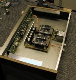
This is only a control unit and nothing else goes inside. It has 3 PS sections: one for display, and two for left and right channel logic. One reason was that I had those small transformers and one wouldn't be big enough. The other is better separation between chanels and microprocessing. It probably doesn't matter much, but who knows?😉
The preamp modules will be built separately and one for ea. channel. This way I can use the best structural environment for line stage sections.
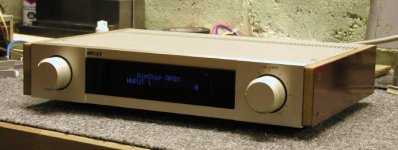
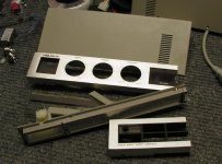
This chassis was built using old Korean made stereo. I liked the knobs with cut outs and the slim profile (less than 2"). I cut out interesting pieces and glued them together to accomodate the size and spacing of Apox control board. The display window was machined out of tinted acrylic on a router. It holds the whole front panel together and is a quite complicated shape. Here's what left from the original unit😉
The preamp modules will be built separately and one for ea. channel. This way I can use the best structural environment for line stage sections.
This chassis was built using old Korean made stereo. I liked the knobs with cut outs and the slim profile (less than 2"). I cut out interesting pieces and glued them together to accomodate the size and spacing of Apox control board. The display window was machined out of tinted acrylic on a router. It holds the whole front panel together and is a quite complicated shape. Here's what left from the original unit😉
Attachments
Member
Joined 2002
Peter,
great cut and paste job! How did you go aboyut masking the white contours of the lcd display? I guess one could use some black tape... By mistake I milled out the panel wider than the window and the white borders of the LCD showed right through the blue acrylic (BAD) so I decided to limit the window size to the size of the display area.
Also I had to limit the countersink and the knob size to 1 inch, the max mill size I had at my disposal. Have I had more time and tools I would have gone for something bigger. The larger proportions you used are more estetically pleasing. 😉
- Status
- Not open for further replies.