harvardian said:I just looked over the software and found the mistake. I will fix and post later today.
If I have time, I will also add the IR selection to disable Sony or Philips modes.
Thanks, I appreciate it.
There's also the issue of not returning to the original volume when it comes out of standby.
Any hope of getting the right button on the encoder to be a mute when pushed quickly, and setup with a push and hold?
Sheldon
Sheldon (and others),
Should the mute functionality be the defacto behavior or should I make it configurable?
I have also found the last volume issue.
Dale
Should the mute functionality be the defacto behavior or should I make it configurable?
I have also found the last volume issue.
Dale
harvardian said:Should the mute functionality be the defacto behavior or should I make it configurable?
I have also found the last volume issue.
Since everybody seems to like somethig different, configurable seems to be a good idea.
It strikes me as a good thing to have because I'll almost never be going into setup after my initial programming and tweaking of the accelerated volume setting.
Sheldon
Do you have any ideas for shield/gnding
Vinnie,
It looks like the noise is coming from the two different power supplies. The secondaries of transformers can float up and down in voltage relative to one another. This presensts a problem when two different floating power supplies are used on the same PCB board. Your stereo is at one ground, and the wall-wart is at another ground. The real solution to this problem, is to somehow common the two grounds of both power supplies. Ideally you would want to do this directly at the output of the voltage regulators.
I've seen some systems where they choose the earths ground.
(The third plug on your A.C. outlet.) and connect all power grounds to this. This will solve your noise problems, but is typically dangerous, because touching your chassis ground, now puts you in a potential shock hazard.
So for a closed stereo or cd player, the only real access point
to the power supply ground, is the signals ground.
So I think the best way to avoid the two power supplies from adding noise to the system, is to attach the audio's ground signal
to the +5V supply ground.
But I would probably connect a 10ohm resistor from signal ground to +5V ground. and put a parallel cap across the 10ohm resistor, rather than a straight wire.
This will keep the DC level of the two supplies from floating around relative to each other, and will help isolate noise from each side. A ferrite bead between the two wil help with high frequency noise.
I hope that helps. 🙂
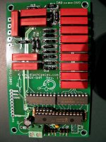
P.S. I think the relays are COTO 8L02-05-10
Good Luck,
Craig Beiferman
Craig,
I think you're correct and this probably explains my problem too.
For my test set-up, I am using the wall wart. For my completed surround preamp, I am planning to use one AC line running into the power supply chassis and from that have at least 2 supplies: one for the audio circuitry and at least one as a dedicated 5 V supply.
How much current do you estimate is required for 5 APOX-2, 7 APOX-IS1 and one APOX-IR1? I want to plan the rating on the 5V regulator(s).
Thanks, Robert
Software update
The latest code has been posted.
Here are the changes:
1) Bug fixes
A) Screen display after standby
B) Last volume after standby
2) Enhancements:
A) Can disable Sony or RC5 modes (YES == Disable)
B) Can enable (ENABLE MUTE E-R) MUTE mode (For sheldon)
If enabled, a short press of volume encoder will toggle mute. To go into config menu, hold down until the first screen appears. Normal toggles after that.
Enjoy...
Dale,
If you find the time, may I suggest you consider the following functionality enhancement:
Configurable boot-up (boot can be either from standby or from off, I am not quite sure if there should be a difference between the two):
a) Boot up at previous level
b) Boot up at pre-set level
c) Boot up at zero level
Also:
a) Boot up in mute
b) Boot up unmuted
Also:
Boot up mute delay [AKA power amp pop killer] (impossible to unmute for 0, 1, 2, 3, 5, 10, 30, 60 seconds)
Also: Display indication of mute status (actively in mute)
Petter
BTW, I like your updated goal ....
Thank you thank you thank you!!!!
You guys are awesome!
😀 😀 😀 😀 😀
I love the pushbutton mute!
BTW your restore volume after standby still doesn't work... 😱 No big deal, I think I like the zero volume at startup anyway.
Sheldon
You guys are awesome!
😀 😀 😀 😀 😀
I love the pushbutton mute!
BTW your restore volume after standby still doesn't work... 😱 No big deal, I think I like the zero volume at startup anyway.
Sheldon
Dale,
Your download worked great! I am using the Phillips code for the Rat Shack 3-in-1 pocket remote (1423) and now it doesn't interfere with my Sony TV. The push button mute is pretty cool too!
Is there a way to delay turning on the opto-darlington in the standby circuit when the apox is powered on from off or standby?
As you know, the opto-darlington feeds a FET that drives my amps power supply relays, and having a little delay (3 seconds or so) would be nice, but is not essential (I am not using an active preamp so I don't get any pops).
Craigl
Thanks for your grounding tips, I'll give it a try now and report my findings!
YOU GUYS ARE GOOD!
-Vinnie
I removed the APOX boards from my stereo and plugged in my laptop to update the software. A couple of glitches in running Bootloader was I had to open the folder containing the program to get it to run, otherwise I got a 'MFC70.DLL' error (or something like that); Win XP couldn't find the .DLL file that was in the same folder.
I finally got it to run, but tried a couple of cables before I could get it to work. I'd bought two, figuring one might work. The modem style didn't work; the straight-thru style of DB9 did. (I'm sure all you Windows-types know this, but us Mac people are easily confused with such things.)
Next, while uploading the software, which went fine and worked well once loaded, I noticed a constant high-pitched clicking sound from the APOX-2 board and both LEDs remained on (were probably flickering really fast). The IR-1 would not change volume setting, but all other features worked, including changing channels on the IS-1 board.
I swapped this APOX-2 (call this board 'A') for the version that had the resistors reversed (board 'B'). This board functioned properly and the volume indicators worked well on the LCD. Guessing that something died on the board A, I swapped IC7 (the one in the 40 pin socket with tape saying 'APOX-2'). B still worked with A's chip, and A was broke with B's chip with same sounds and both LEDs still on.
So, are the relay driver(s) on board A dead? There's not much else to go wrong. With all the ground jumpering (using leads with alligator clips), did some of the ULN2803A get fried?
Thanks for any help, Robert
Hi Robert,
Could you do the following test for me:
Put the "bad" board in the system.
1) When you turn on the power, do the leds flash?
2) When you increase the volume, do any of the leds flash very briefly?
3) If there is only one volume board in the system, do you get a "no volume board" message. (May have to turn off standby mode).
It is interesting that the micro from the bad board functions correctly in the good board. I would have suspected that it is this chip that was damaged. The LED tests should give me more information.
Please email me. I think that you may need some replacement kits.
rljones said:[B The modem style didn't work; the straight-thru style of DB9 did. (I'm sure all you Windows-types know this, but us Mac people are easily confused with such things.)
[/B]
That's a pet peeve of mine, it's not "MAC" people, it's people with a lack of hardware experience.
I'm a mac people and I'm quite familiar with the RS422 serial ports on old macs. In fact I just got a USB to serial adapter working under os X that wasn't supposed to work.
Macs get a bad rep because of that sort of percerption
Sheldon
Apox...
If I understand this right; can I add several input & volume boards for a multi-channel setup?
Can there be; 4 pair XLR inputs, 4 pair RCA, AND a 5+1 in/output?
And, can I mix volume-controller boards? (const.imp for Stereo/chip for multi-channel?)
Arne K
If I understand this right; can I add several input & volume boards for a multi-channel setup?
Can there be; 4 pair XLR inputs, 4 pair RCA, AND a 5+1 in/output?
And, can I mix volume-controller boards? (const.imp for Stereo/chip for multi-channel?)
Arne K
Dale,
1. The LEDs on the 'bad' board start flasing as soon as they get power, even before the IR1 has clicked on into standby.
2. When I change volume with the bad board connected, the IR1 doesn't change from 0 on the display, and both LEDs on the bad board _never_ stop flashing (they're going so fast they seem to be constantly on).
3. I've only tried with one volume board at a time. No vol board appropriately gives a "No Volume Board" message; the good or bad volume boards do not give this message.
Sheldon,
I was saying that in jest while being self-deprecating. I've programmed in Pascal and some C, and a bit in assembly, during the mid-80s--all on PCs. I switched to Mac for graphics soon after, networking my office by my lonesome. I just dislike futzing with crossed this and crossed that cables. Isn't that why there is Windows: "plug and play", no thought required?
Regards, Robert (who is now going to stumble to the kitchen in an attempt to turn on the expresso maker...)
Hi Arne,
In theory that system would work. I need to make a proposed diagram for these multi-channel systems. I also need to make some software changes for multi-channel mode with different volume boards. Right now, only one type of board in a system is supported. This would not be a major change.
On my plate right now:
1) Special software for customer in Austria.
2) Test APOX-SHM board (then ship out kits if all goes well)
3) Minor software changes (add delays, fix standby volume restore)
4) Develop a multi-channel scenario and implement software.
5) Kick Craig's behind to finish APOX-PGA
Dale
Robert,
Obviously something is wrong. For the leds to be constantly flashing, it is possible that the micro keeps reseting due to a "brownout" or stack overflow condition. I am surprised that the message does not appear, but the volume stays at zero?
I have no theories, but it is possible that when the micro turns on one of the relay drivers, it causes the voltage to drop and create the reset.
The ULN2803A are pretty indestructable. I cannot believe that even reversing the 5V would damage them.
Is it possible that the 5V power was reversed? It may be as simple as a bad capacitor.
1) Try removing the 100uF electrolytic cap.
Do you have a scope?
Look at pin 1 of the micro, does it stay at 5V?
There was no reversal of 5V (I didn't touch any wrong parts). I was just wondering if lifting the ground on/off, damaged something by static electricity.
Near the end of testing for the hum, these same LEDs did flicker a lot but settled down and I didn't think anything of it. Now they don't stop.
I do have a scope; I'll check pin 1 voltage; and replacing the cap is no problem.
I'll get back soon, robert
Near the end of testing for the hum, these same LEDs did flicker a lot but settled down and I didn't think anything of it. Now they don't stop.
I do have a scope; I'll check pin 1 voltage; and replacing the cap is no problem.
I'll get back soon, robert
pin 1 of micro is at 1.1V.
When make the measurement, the flicker rates slows and the 'sound' of the LEDs (it sounds like the noise is coming from the LEDs; not the relays) decreases in pitch.
When make the measurement, the flicker rates slows and the 'sound' of the LEDs (it sounds like the noise is coming from the LEDs; not the relays) decreases in pitch.
Robert,
That is not good. Pin 1 should be at 5V. This is the reset line. I am not sure if the micro brings this line low if it generates a reset internally. Try this experiment since you are likely to return the boards anyways. Gently Lift pin 1 from the socket. Solder a 10K resistor to it and solder the other end of the resistor to +5V.
Power up the board and look at pin 1. Does it stay at a constant 1.1V or does it cycle?
Dale
- Status
- Not open for further replies.