mikesnowdon said:Any news on my enquiry yet? You were going to look at the connection of the TC9163 to the Input1 board for me.
Yes, you'll get it in a couple of days.
Best regards,
Mikkel C. Simonsen
Renron said:I have finished building the Control1 combined with the Input4 and could not be more pleased with the quality of the kits. The boards were well thought out and professionally layed out. Very good Job!
Thanks!
On page 4 of the manual, under Connection Headers it states;
" JP9-12 are used for connecting a linestage and/or volume control. JP11 and 12 are outputs and JP9 and 10 are inputs."
Are these "JP9-10" pinouts used as a jumper block? or as (wire) connection points for preamp left and right channels?
They are connection points for your volume control.
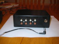
There are 4 RCA type jacks on the back of the unit, and none of them are labeled in the manual or the schematic. ( I tried to understand the schematic but I'm too newb.) The Input4 Introduction states; "This circuit is input selector with three inputs and mute. There are also outputs for a power relay and an additional relay." If only 3 of the 4 RCA jacks are inputs is the 4th one the output? If so which one?
There are three inputs and one output. When looking at the connectors from left to right they are out, in3, in2 and in1.
Or was it designed to be built into an amplifer and not a stand alone Input switched box?
It can be used for both.
One question though, What is the 4th input for? It has a different set of resistor values than 1 - 3 ? Phono?
No, the 4th input is the output 🙂
Best regards,
Mikkel C. Simonsen
Telstar said:I asked George and pointed him to this thread.
I dont use balanced... let's see what can be done 🙂
What I can make you is a control board with LED display for volume setting, a LED display for input setting (if you use an input selector also) and remote control receiver. You can select 1dB, 2dB or even 0.5dB steps, but you will have to store these steps yourself. It can be done - I've tried 🙂
Best regards,
Mikkel C. Simonsen
Mikkel,
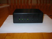
Thanks for the reply, I used a pair of jumpers to enable the outputs on the back. Everything works perfectly now. Thank you for a very good quality pair of boards. I built them into an El Cheapo box from Rat Shack, the boards stay cool without any venting, and the remote IR works from ~6 meters away........have not tested at any further range than that, but may work at longer ranges.
I have attached pictures to show the size of the box. It is not the best looking box but serves it's purpose and it was cheap!
Thanks Mikkel, I will report on the remote volume control when I have finished building and installing it.
Ron
Attachments
8 channels
Hello Mikkel.
Is there possible to make an 1 in 1 out 8 ch volume control using 4 ChipVol1 and Control2 with balance for all channels?
I have most of the parts for ChipVol1, is it possible to buy only the PCB? and what would it cost?
What would i need more?
Thanks // David
Hello Mikkel.
Is there possible to make an 1 in 1 out 8 ch volume control using 4 ChipVol1 and Control2 with balance for all channels?
I have most of the parts for ChipVol1, is it possible to buy only the PCB? and what would it cost?
What would i need more?
Thanks // David
Re: 8 channels
Yes.
I have just added the PCB-only option to the website.
A display, 12-15V AC and 5V DC.
Best regards,
Mikkel C. Simonsen
pekkari said:Is there possible to make an 1 in 1 out 8 ch volume control using 4 ChipVol1 and Control2 with balance for all channels?
Yes.
I have most of the parts for ChipVol1, is it possible to buy only the PCB? and what would it cost?
I have just added the PCB-only option to the website.
What would i need more?
A display, 12-15V AC and 5V DC.
Best regards,
Mikkel C. Simonsen
Thanks
Thanks.
Is frontpanel 2 better than frontpanel 1 for me?
Do you have a part list for the chipvolume?
Can i use both 24*2 display and 16*2?
Thanks // David
Thanks.
Is frontpanel 2 better than frontpanel 1 for me?
Do you have a part list for the chipvolume?
Can i use both 24*2 display and 16*2?
Thanks // David
Re: Thanks
You don't need all the input select buttons on the frontpanel, so you may as well choose the type 2.
Yes.
Part list
Reference Part Marking/notes
R2,R3 ............. 100R resistor ..................... brown - black - black - black - brown
R4,R5 ............. 100k resistor ..................... brown - black - black - orange - brown
R6................... 10k resistor ....................... brown - black - orange - gold
R7,R8 ............. 931R resistor ..................... white - orange - brown - black - brown
R9,R10 ........... 105R resistor ..................... brown - black - green - black - brown
C5................... 100nF ceramic SMD cap .. no marking
R1................... 10k resistor network .......... something including 103
IC1.................. Dual op. amp (input buffer)
U1................... PGA2310 attenuator chip
F1 ................... Filter
D1,D2 ............. MBR160 Schottky diode
C7-C8,C11-C12 100nF polyester cap ......... 104, 100n etc.
L1 ................... Ferrite bead
JP7 ................. AC in power connector ...... 2-pole screw terminal
JP8 ................. DC in power connector...... 2-pole screw terminal
JP1 ................. SPI serial control port ........ 10-pin header
JP2-JP5 .......... In/out headers ................... 2-pin header
JP6 ................. Setup header .................... 2-pin header
C3-C4,C6,C9-C10,
C13-C16 ......... 10µF 25-35V electrolytic ... 10/25V, 10µF 35V etc.
Q1 .................. NPN transistor................... C547B, BC237B, C36, C37 etc.
U2................... LM317 voltage regulator
U3................... LM337 voltage regulator
C1,C2 ............. 2m2 25V electrolytic .......... 2200µF 25V, 2200/25 etc.
Yes - but only one at a time 🙂
Best regards,
Mikkel C. Simonsen
pekkari said:Is frontpanel 2 better than frontpanel 1 for me?
You don't need all the input select buttons on the frontpanel, so you may as well choose the type 2.
Do you have a part list for the chipvolume?
Yes.
Part list
Reference Part Marking/notes
R2,R3 ............. 100R resistor ..................... brown - black - black - black - brown
R4,R5 ............. 100k resistor ..................... brown - black - black - orange - brown
R6................... 10k resistor ....................... brown - black - orange - gold
R7,R8 ............. 931R resistor ..................... white - orange - brown - black - brown
R9,R10 ........... 105R resistor ..................... brown - black - green - black - brown
C5................... 100nF ceramic SMD cap .. no marking
R1................... 10k resistor network .......... something including 103
IC1.................. Dual op. amp (input buffer)
U1................... PGA2310 attenuator chip
F1 ................... Filter
D1,D2 ............. MBR160 Schottky diode
C7-C8,C11-C12 100nF polyester cap ......... 104, 100n etc.
L1 ................... Ferrite bead
JP7 ................. AC in power connector ...... 2-pole screw terminal
JP8 ................. DC in power connector...... 2-pole screw terminal
JP1 ................. SPI serial control port ........ 10-pin header
JP2-JP5 .......... In/out headers ................... 2-pin header
JP6 ................. Setup header .................... 2-pin header
C3-C4,C6,C9-C10,
C13-C16 ......... 10µF 25-35V electrolytic ... 10/25V, 10µF 35V etc.
Q1 .................. NPN transistor................... C547B, BC237B, C36, C37 etc.
U2................... LM317 voltage regulator
U3................... LM337 voltage regulator
C1,C2 ............. 2m2 25V electrolytic .......... 2200µF 25V, 2200/25 etc.
Can i use both 24*2 display and 16*2?
Yes - but only one at a time 🙂
Best regards,
Mikkel C. Simonsen
More questions
Hello Mikkel.
And thanks for the reply, i have a few more questions for you.
Can i replace C1 and C2 on Chipvol for a Elma 3300uF 25V with a diameter of 16mm?
If i want, can i replace the powersuplies on each chipvol1 board with one 317337PSU?
If i want 5v from a 317PSU can i feed it with 15V AC?
I guess that the F1 filter is something like this: https://www1.elfa.se/elfa~dk_da/b2b/catalogstart.do?tab=catalog
Which one is has the right value?
Can i use this display: http://www.fractronics.com/Samsung16T202DA1E.pdf?
Thank You.
// David
Sorry its me again.
I just got 2 transformers from a friend, and they are 2x9V if i connect the 2 outputs i got 18v AC. Is chipvolume1 able to handle 18V?
Im having some trouble to find the MBR160 Schottky diode, could be replaced whit any other diodes and what type is that?
Thanks // David
I just got 2 transformers from a friend, and they are 2x9V if i connect the 2 outputs i got 18v AC. Is chipvolume1 able to handle 18V?
Im having some trouble to find the MBR160 Schottky diode, could be replaced whit any other diodes and what type is that?
Thanks // David
Hello,
I'am the happy owner of some relvol3 boards, and i am lookinf for some advice.
My relvol3 is 2*10k and i will use them with hypex UCD 100k input), does someone can help my with the load resistor formula for R27 and R28?
Is there a special wire needed to connet to Relvol3 on the same outpout of the control2 board or is it the same?
Thanks a lot
Anthony
Re: More questions
You still need two caps, so you would have to fit them a bit above the board (there's only space for 12mm caps).
Yes. The 10µF caps on each ChipVol1 board is enough local decoupling.
Yes. You just need a bigger heatsink.
No idea - links to the Elfa website don't work 🙂
It's a type with two ferrite beads and a 47-100nF cap.
Yes. But be careful when you connect it. You have to put the connector on top of the display board - otherwise the connector will be mirrored, and you have to make a "twister pair" cable...
Not with the standard 25V electrolytics. But if you use a shared 317337PSU it will work fine.
They are also called SB160 and many other things. It's just a 60V 1A Schottky-diode - any type will do. If you use the shared PSU, you won't need them.
Best regards,
Mikkel C. Simonsen
pekkari said:Can i replace C1 and C2 on Chipvol for a Elma 3300uF 25V with a diameter of 16mm?
You still need two caps, so you would have to fit them a bit above the board (there's only space for 12mm caps).
If i want, can i replace the powersuplies on each chipvol1 board with one 317337PSU?
Yes. The 10µF caps on each ChipVol1 board is enough local decoupling.
If i want 5v from a 317PSU can i feed it with 15V AC?
Yes. You just need a bigger heatsink.
I guess that the F1 filter is something like this: https://www1.elfa.se/elfa~dk_da/b2b/catalogstart.do?tab=catalog
Which one is has the right value?
No idea - links to the Elfa website don't work 🙂
It's a type with two ferrite beads and a 47-100nF cap.
Can i use this display: http://www.fractronics.com/Samsung16T202DA1E.pdf?
Yes. But be careful when you connect it. You have to put the connector on top of the display board - otherwise the connector will be mirrored, and you have to make a "twister pair" cable...
I just got 2 transformers from a friend, and they are 2x9V if i connect the 2 outputs i got 18v AC. Is chipvolume1 able to handle 18V?
Not with the standard 25V electrolytics. But if you use a shared 317337PSU it will work fine.
Im having some trouble to find the MBR160 Schottky diode, could be replaced whit any other diodes and what type is that?
They are also called SB160 and many other things. It's just a 60V 1A Schottky-diode - any type will do. If you use the shared PSU, you won't need them.
Best regards,
Mikkel C. Simonsen
dede said:I'am the happy owner of some relvol3 boards, and i am lookinf for some advice.
My relvol3 is 2*10k and i will use them with hypex UCD 100k input), does someone can help my with the load resistor formula for R27 and R28?
You need (10^-1 - 100^-1)^-1 = 11k1 for that.
Is there a special wire needed to connet to Relvol3 on the same outpout of the control2 board or is it the same?
To connect more than one RelVol1/3 board to one port, you can just but more 10-pole connectors in parallel on the ribbon cable.
Best regards,
Mikkel C. Simonsen
Hi Mikkel. I read a few pages of this thread but like any good DIYaudio thread it`s wayyyy too long...
Anyway I`ve confused myself:
If I wanted an LCD diplayed control. I would need:
-Control 2
-Front Panel Type 2 (I like knobs...)
-LCD2RB (for a red display)
What else? What're the power requirements? Also, on a scale of 1-10, 1 being idiot and 10 being you, how much skill is needed for this arrangement to be integrated into a simplistic ss preamp?
raypalmer said:If I wanted an LCD diplayed control. I would need:
-Control 2
-Front Panel Type 2 (I like knobs...)
-LCD2RB (for a red display)
What else? What're the power requirements?
For the above parts only 5V DC.
Also, on a scale of 1-10, 1 being idiot and 10 being you, how much skill is needed for this arrangement to be integrated into a simplistic ss preamp?
What input selector (if needed) and attenuator do you plan to use?
You do need some soldering skills to get the boards assembled. Apart from that I don't think it's that difficult.
Best regards,
Mikkel C. Simonsen
raypalmer said:
Also, on a scale of 1-10, 1 being idiot and 10 being you, how much skill is needed for this arrangement to be integrated into a simplistic ss preamp?
Being a rank amateur at electronics myself, I am qualified to answer this question.
My soldering skills are good, not great, but good, I can read a schematic and tell you what parts match which symbols. But I could not and do not understand why most of these circuits work the way they do.
I just (successfully) built my first power supply with my own design. Nothing fancy and I used a 3 legged regulator, so some would say that's cheating. OK, I cheated.
On a scale of 1-10, if you know which end of the soldering iron to hold and can solder reasonably well, give it a go. You'll learn quite a bit while building the device and it's fun too. Mikkel's boards are high quality and his kits are too, you may have to read the manual a few times to understand what is said, and if you don't, he is here to help with questions. He was always timely to answer my questions both on this board and private emails.
I'm probably a 3 on your scale and I've built (successfully) 4 of his kits. Give it a whirl.
One note, shipping is NOT fast................snore..............be patient, mine took 7 weeks to arrive. I did however order a special part that Mikkel told me would take time to source, I expected a long wait.
Happy Customer,
Ron
- Home
- Vendor's Bazaar
- Remote control kits