well, there are a lot of discussions on this subject, don't want to start one here, but as far as I know this is only an issue on power tubes.Might this cause cathode stripping?
With these type of tubes (pre- and poweramp tubes), at the voltages used, cathode stripping is non-existent. Cathode poisoning though, could (but not always) occur when leaving the heater on for several hours without any HT, depending on the type and quality of the tube. So running the tubes with full HT without the heater is no problem. But like DjMiddelKoop said, that's not the issue of the thread 🙂Might this cause cathode stripping?
Agreed, but what about the moment the relay contacts need to be disengaged with the full voltage across them? Wouldn't that cause problem?In your OP you stated that you are only intending on switching out the current limiting resistor. If that is all you are doing, then you are not actually switching the full HT voltage, only the voltage that is dropped across the resistor. Of course the relay will need to be insulated from other parts of the circuit but that is generally not an issue.
Last edited:
You want to switch the soft-start resistor *out* of the circuit.
The real danger with high DC voltage switching is the formation of arcs upon contact opening. Why not make sure that the relay stays closed until the DC has dropped significantly during power-off?
A planned power-off sequence is sometimes just as useful and important as in the start-up case.
Rundmaus
EDIT:
If it is a soft-start current limiting resistor I can not imagine a normal operation condition in which it will be needed to switch the resistor back in under full DC voltage.Agreed, but what about the moment the relay contacts need to be disengaged with the full voltage across them?
Last edited:
Just about everyone has missed it...
This i the PERFECT example of where to use a reed switch. The glass-ampule sealed ones are just the ticket - with the right clearance, they can withstand thousands of volts ... relative to their surrounding coil, and when asked to short-out the inrush resistor, they can handle the few dozen DIFFERENTIAL volts across it just fine. Opening, or closing. They are however, with rare exception, NOT good at switching many hundreds of DC or AC volts. And they're tiny. And not very expensive. And PCBoard mountable. And low drive current. Really quite nice!
Of course, another of the many options is to think out of the box here ... and put the "inrush limit resistor" in the ground-side of the power supply (since current doesn't know in the slightest where the resistor is in a current-loop), and, given its low voltage potential (ground +/- a few volts) ... then you could just use a conventional low-voltage PCboard type relay. Or a front-panel switch for that matter. Why not? Indeed... a front panel slow-start switch.
Or again, thinking outside the box, get rid of the inrush-current limit resistor, and replace it with the most time-proven device to do a better job: the choke. Resistors, after all, are just "chokes on the cheap". And since you obviously aren't being "cheap" here (7 amps of heaters and 1000 uF of 530 volt capacitance!) ... why bother with the inrush resistor at all? Just go for the golden part: 1H to 10H chokes. Their series resistance can be 1/10th to 1/100th that of your "inrush resistor", but their reactance makes them great at keeping the ampere flow steady and happy. Makes for nice on your rectifier chain.
Or, heck ... do both! Inrush resistor on the ground-side, chokes on the hot side, little R-C timer for the inrush bypass, front panel defeat and a nice red-green pair of complimentary LEDs on the front panel to indicate whether the bypass is engaged or defeated.
And, just to be a bit perfectionist in this ... there are these things called "constant current circuits", my friend. Say your B+ is supposed to be humming along (nominally) at 250 ma (at 500V). Putting a 1000 ma current-source in place of the resistor has a huge benefit, of course in that it changes its dynamic 'resistance' (actually impedance) to match the current flow. When the demand is high, it acts as a current-source. When the demand drops below the limit, its impedance drops (and thus it 'cuts itself out of the circuit').
The Box has tall walls. But there is much outside the box worth considering.
GoatGuy
EDIT: Oh yes ... then there is the zener-plus-resistor bypassed ground-side current source idea that can use (like the situation with the low-voltage relay), a low-voltage regulator too ... and safely deal with the hundreds of volts that "inrush" might entail. Again ... just need to get more creative in the circuit-to-solve department.
Last edited:
Good point. If the voltage drop is close to nothing, there essentially is no voltage to switch. However, even though switching will occur at low voltage, the contacts must withstand full voltage initially and may arc.In your OP you stated that you are only intending on switching out the current limiting resistor. If that is all you are doing, then you are not actually switching the full HT voltage, only the voltage that is dropped across the resistor. Of course the relay will need to be insulated from other parts of the circuit but that is generally not an issue.
Good point. If the voltage drop is close to nothing, there essentially is no voltage to switch. However, even though switching will occur at low voltage, the contacts must withstand full voltage initially and may arc.
See my comment just above yours. The "relative voltage problem" is easily handled both by a zener diode and reed relay, AND moving the whole thing to the ground-side (to get rid of the relatively high voltage).
Assumed that the current limiting resistor fails someday, a tiny reed switch will give an impressive arc lamp upon trying to switch 500+ volts with that much capacitance behind it. As a bonus, it will probably explode violently and send glass shards into the surrounding circuitry.
For the sake of safe operation, I would only recommend two approaches:
a) Primary side switching: involves 'only' mains voltage instead of arc-prone DC and no high capacitances, or ...
b) a beefy choke in the HV line. But to behave as an inrush suppressor, this must be one hell of a choke. Not cheap. But as a side effect, makes nice DC and a lot of your filtering capacitance is then obsolete.
Rundmaus
The use of the Zener protects the relay, but negates the point of soft-start...See my comment just above yours. The "relative voltage problem" is easily handled both by a zener diode and reed relay, AND moving the whole thing to the ground-side (to get rid of the relatively high voltage).
This is where my limited knowledge fails me 🙂. I always thought the caps were 'bottomless pits' at startup, and a resistor in ground wouldn't do the inrush any good.Of course, another of the many options is to think out of the box here ... and put the "inrush limit resistor" in the ground-side of the power supply (since current doesn't know in the slightest where the resistor is in a current-loop), and, given its low voltage potential (ground +/- a few volts) ...
That's an awesome idea, but at these voltages, it should be a FET driven CCS??And, just to be a bit perfectionist in this ... there are these things called "constant current circuits", my friend. Say your B+ is supposed to be humming along (nominally) at 250 ma (at 500V). Putting a 1000 ma current-source in place of the resistor has a huge benefit, of course in that it changes its dynamic 'resistance' (actually impedance) to match the current flow. When the demand is high, it acts as a current-source. When the demand drops below the limit, its impedance drops (and thus it 'cuts itself out of the circuit').
Up until a couple of months ago, I didn't even know there was a box! 😛The Box has tall walls. But there is much outside the box worth considering.
But thanks for the food for thought!
Good point. If the voltage drop is close to nothing, there essentially is no voltage to switch. However, even though switching will occur at low voltage, the contacts must withstand full voltage initially and may arc.
They are never going to arc because the resistor is keeping the voltage to a low value.
Trying to design a circuit to survive a failure is a completely different kettle of fish. making the resistor up of a number of over specified resistors is one way to keep thing safe.
Maybe not...
See:
The use of the Zener protects the relay, but negates the point of soft-start...
See:
Attachments
And PS: I still like CCS's better, as the self-adjusting device of choice. No reed relay, no craziness with Zeners, fiddling with resistance values. Has to take high voltage - but that, these days - is what power MOSFETs do so well. We got 'em, and we might as well use 'em. Especially since they're so darn cheap. The filter caps will remove any "sonic signature" they might impart.
GoatGuy
EDIT: Consider the STF3LN62K3 (mouser, ST eletronics, 620V breakdown, TO220 package, good range of gate ON characteristics.) $0.82 ... or "pretty darn cheap". Combine with a normally-off mode, and a slow-start gate capacitor with trickle-charge on it from raw hi V ... (3.3 uF, 22 megohm, off the +600 volt side of things, for a 22 second RC constant, which at Vcutoff = 3.75 v and 600 V charge = 0.8 seconds, and to reach the full gate of 10V [effectively 3 ohms passthru], takes only about 1 second longer. The perfect slow-start switch! Use the device's built-in zener for gate protection, with the 22 megohm resistor cutting current to 27 microamps. Quite within the range of the device.
NEEDED:
1 3.3 uF, 50V electrolytic cap
1 22M, 1/4 watt resistor
1 STF3LN62K3 MOSFET
And nothing more. The absolute in simplicity, and low cost. And fault tolerance, and reliability. Woot!
Last edited:
Trying to design a circuit to survive a failure is a completely different kettle of fish.
Making a design fail-proof is almost impossible. But in the design process, one should at least think about possible failure modes of parts that handle significant current, voltage or stored energy.
Identifying possible failure modes and evaluating their consequences might minimize the amount of smoke and fire in a failure event, if appropriate measures are taken.
making the resistor up of a number of over specified resistors is one way to keep thing safe.
Sounds like a good idea.
Rundmaus
Except at initial power on. The voltage across the resistor is full voltage...They are never going to arc because the resistor is keeping the voltage to a low value.
Still the same problem... Full voltage at initial power up. The Zener won't clamp the contact voltage that way.See:
In your OP you stated that you are only intending on switching out the current limiting resistor. If that is all you are doing, then you are not actually switching the full HT voltage, only the voltage that is dropped across the resistor. Of course the relay will need to be insulated from other parts of the circuit but that is generally not an issue.
and award of true answer goes to..
IMPOSSIBLE. Reference Ohms Law. Or if in doubt read Kirchoffs laws.Except at initial power on. The voltage across the resistor is full voltage...
Last edited:
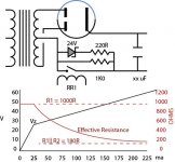
IMPOSSIBLE Reference a simple RC circuit:IMPOSSIBLE. Reference Ohms Law.
Vs = Vr + Vcap
Setting Vcap to 0 at initial powerup:
Vs = Vr + 0
Vs = Vr
If Vcap = 0, then Vr must be the full supply voltage. Since the relay is across R, the full supply voltage is initially present. It falls to zero exponentially.
- Status
- Not open for further replies.
- Home
- Amplifiers
- Tubes / Valves
- Relays for tube voltages