I have built a few relay attenuators and I am very happy about the latest version.
However, one thing that I have not been 100% satisfied with is that there is no way of switching the relais during a zero crossing.
This can sometimes lead to glitches in the output, it is a common issue with all relay based attenuators and there is no easy fix for it.
Relais are just too slow and unpredictable for it to work.
I have thought about this problem for a long time and had a few ideas that I considered but nothing really seems feasible.
But then I got an idea.
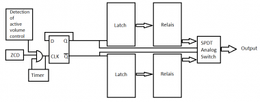
What if you combine 2 relay attenuators and use an SPDT analog switch at the output of both.
The idea is that you start with the analog switch selecting Att. 1, this is your current volume setting.
You then change the volume of Att. 2, when that is done you wait for the zero crossing and the analog switch now selects the output of Att. 2.
Att. 2 is now selected and the volume level has now changed.
Now, if the analog switch is only allowed to switch between the 2 attenuators during a zero crossing, the final drawback with relay attenuators would be solved.
You continously switch between the 2 attenuators while you are changing volume, but only during zero crossings.
I have not done any schematic work yet, but I have a few ideas of how to implement it.
Am I totally crazy?
However, one thing that I have not been 100% satisfied with is that there is no way of switching the relais during a zero crossing.
This can sometimes lead to glitches in the output, it is a common issue with all relay based attenuators and there is no easy fix for it.
Relais are just too slow and unpredictable for it to work.
I have thought about this problem for a long time and had a few ideas that I considered but nothing really seems feasible.
But then I got an idea.
What if you combine 2 relay attenuators and use an SPDT analog switch at the output of both.
The idea is that you start with the analog switch selecting Att. 1, this is your current volume setting.
You then change the volume of Att. 2, when that is done you wait for the zero crossing and the analog switch now selects the output of Att. 2.
Att. 2 is now selected and the volume level has now changed.
Now, if the analog switch is only allowed to switch between the 2 attenuators during a zero crossing, the final drawback with relay attenuators would be solved.
You continously switch between the 2 attenuators while you are changing volume, but only during zero crossings.
I have not done any schematic work yet, but I have a few ideas of how to implement it.
Am I totally crazy?
Last edited:
Why do you use relays for the attenuators rather than (electronic) analogue switches? If the reason is that you want to avoid the distortion of the analogue switches, then you need some sort of relay-based bypass for the analogue SPDT switch.
I don't know precisely how, but essentially, while you are listening at a constant volume setting, the relay-based bypass circuit would remove the analogue SPDT switch from the signal path. When you change volume, first the bypass switches the analogue SPDT switch in the circuit, then the analogue SPDT switch switches at a zero crossing and then the bypass removes the analogue SPDT switch from the signal path again.
I don't know precisely how, but essentially, while you are listening at a constant volume setting, the relay-based bypass circuit would remove the analogue SPDT switch from the signal path. When you change volume, first the bypass switches the analogue SPDT switch in the circuit, then the analogue SPDT switch switches at a zero crossing and then the bypass removes the analogue SPDT switch from the signal path again.
Why do you use relays for the attenuators rather than (electronic) analogue switches? If the reason is that you want to avoid the distortion of the analogue switches, then you need some sort of relay-based bypass for the analogue SPDT switch.
I am thinking about having an opamp buffer after each attenuator.
Then I can place the SPDT analog switch after the buffers and then if the next stage has a FET input, it is then possbile to use a very high value resistor to ground after the analog switch. This would minimize the voltage across the switch and reduce the distortion.
With a decently low RDSon analog switch it should work fine. I am also considering building my own discrete analog switch, there are FET on the market now, with extremely low RDSon, less than 1mOhm in some cases and this solves the distortion issue. Although the switching speed might be an isse for those.
But like I said, it is just an idea at the moment and the specific implementation is still something I am working on.
Last edited:
I don't know precisely how, but essentially, while you are listening at a constant volume setting, the relay-based bypass circuit would remove the analogue SPDT switch from the signal path. When you change volume, first the bypass switches the analogue SPDT switch in the circuit, then the analogue SPDT switch switches at a zero crossing and then the bypass removes the analogue SPDT switch from the signal path again.
A relay bypass is an interesting idea as well.
But it is still only an idea that I am toying with. It might never see the light of day in the end.
Then I can place the SPDT analog switch after the buffers and then if the next stage has a FET input, it is then possbile to use a very high value resistor to ground after the analog switch. This would minimize the voltage across the switch and reduce the distortion.
Quick calculation using an analog switch with a maximum RDSon of 100 Ohm, with a 1Meg resistor to ground after it. Then only 0.0001% of the signal voltage will be across the analog switch. If we assume a 10Vrms signal, then only 10uVrms would develop across the analog switch. On top of that, most analog switches have a resistance that typically varies a maximum of 10% or lower over the whole analog signal range. So worst case you get a modulated signal that is the equivalent of 1uVrms out of 10Vrms. Distortion is not an issue.
With an analog switch with even lower Rdson, the 1Meg resistor to ground could be reduced to a lower value if needed.
Edit : Did not think about leakage current of the analog switch, that might be an issue.
Edit2 : The way I am considering using the analog switch, with an opamp buffer between it and the output of the attenuators it should not be a problem, there will always be a low impedenca path to ground. Connecting the output of the attenuator buffers to NC and NO of the analog switch and using the COM as output. Leakage current on the NC and NO side of the switch will always have a low impedance path to ground, the opamp buffers just sinks the current and that is not an issue. On the COM saide of the switch there would be the 1Meg resistor to ground but there will always be a low impedance path through either the NC or NO switch, depending on switch position. So the impedance would always be the switch ON resistance in parallel with 1Meg. So continuing using my 100Ohm switch as an example, the impedance would be 100//1Meg = 100Ohm. Not an issue either.
Last edited:
MAX4959/4960 would be a good candidate, max 25Ohm Ron and max 1.5Ohm flatness. Distortion with a 600Ohm load is 0.005%, with a 1Meg load=practically unmeasurable. They also feature MBB.
Here is a 20 ohm DIP mosfet relay, $5.60 ea. https://www.newark.com/ixys-semiconductor/lcc120/ssr-opto-mosfet-250v-170ma/dp/04M4560
With a section of a 393 comparator, to detect 0 v, and a nor gate, (2 inputs low is high out) you should be able to build a low voltage turn on control. Turn off will still pop, though.
With a section of a 393 comparator, to detect 0 v, and a nor gate, (2 inputs low is high out) you should be able to build a low voltage turn on control. Turn off will still pop, though.
Why do you use relays for the attenuators rather than (electronic) analogue switches? If the reason is that you want to avoid the distortion of the analogue switches, then you need some sort of relay-based bypass for the analogue SPDT switch.
I don't know precisely how, but essentially, while you are listening at a constant volume setting, the relay-based bypass circuit would remove the analogue SPDT switch from the signal path. When you change volume, first the bypass switches the analogue SPDT switch in the circuit, then the analogue SPDT switch switches at a zero crossing and then the bypass removes the analogue SPDT switch from the signal path again.
Or just use one relay set and a log pot, and an encoder on the pot shaft. When the pot is moving switch out the relays, once the pot is stable use the encoder to set the relay attenuator and switch it back into control, disconnecting the pot.
Last edited:
Why making things more complex as needed with a second analogue path.
I assume you want to prevent pops and clicks when changing volume with your relays, right ?
Suppose that 00..00 is your lowest volume and 11..11 the highest.
Also take A msec as the time for your relay to switch.
Now when changing volume let all relays going from 1 to 0 execute this without delay, but all relays going from 0 to 1 with a delay of slightly more than A msec.
Now going from 011..11 to 100..00 means in fact that a step in between of 000..00 is taken.
Going back from 100..00 to 011..11 has also a step in between of 000..00, preventing any pop or click.
I have used this successfully in several designs that are all completely free of disturbing clicks.
Hans
Why making things more complex as needed with a second analogue path.
I assume you want to prevent pops and clicks when changing volume with your relays, right ?
Suppose that 00..00 is your lowest volume and 11..11 the highest.
Also take A msec as the time for your relay to switch.
Now when changing volume let all relays going from 1 to 0 execute this without delay, but all relays going from 0 to 1 with a delay of slightly more than A msec.
Now going from 011..11 to 100..00 means in fact that a step in between of 000..00 is taken.
Going back from 100..00 to 011..11 has also a step in between of 000..00, preventing any pop or click.
I have used this successfully in several designs that are all completely free of disturbing clicks.
Hans
Your suggestion is already what I am doing in my current attenuator and it works great. However since the relays do not switch at the zero crossing there will still be slightly audible glitches at times. It rarely happens but getting rid of it would be the ultimate relay attenuator solution.
My current solution : Pop/click free HW-based relay attenuator V3
But there are still improvements to be made and implementing a second audio path + zero crossing would be the next step up in the evolution of relay based attenuators.
Last edited:
Hi,
in my relay attenuators I just muted the output with another relay for a couple of msecs.
No glitches no transitions audible whatsoever
Using a analog switch for muting would probabely be even softer.
jauu
Calvin
in my relay attenuators I just muted the output with another relay for a couple of msecs.
No glitches no transitions audible whatsoever
Using a analog switch for muting would probabely be even softer.
jauu
Calvin
Hi,
in my relay attenuators I just muted the output with another relay for a couple of msecs.
No glitches no transitions audible whatsoever
Using a analog switch for muting would probabely be even softer.
jauu
Calvin
That still does not solve the issue that the output mute relay might be switched on at the top of the waveform.
If you have a peak of lets say 5V and you switch the relay on at the top, the output signal would go from 0-5V in an instant and would be the equivalent of a DC transient.
But like I said, my current attenuator has dual state switching without an output mute relay and it works fine.
There are some small audible glitches at times, but it only happens when I play bass heavy music and turn the volume up where it isnt really comfortable.
Anyway, this project is shelved for the moment, since I am working on changing my current attenuator design control circuit from pot+ADC to optical Rotary Encoder+counter instead.
Hi,
I´ve never experienced any serious glitches and hardly any audible ones at all.
In the situation You describe the rise of the signal would be so steep that the frequency would be in the inaudible ultrasonic range.
I think the extra effort for zero-crossing is not necessary in praxis but anyway, proceed as you wish 😉
jauu
Calvin
Hi,
I´ve never experienced any serious glitches and hardly any audible ones at all.
In the situation You describe the rise of the signal would be so steep that the frequency would be in the inaudible ultrasonic range.
I think the extra effort for zero-crossing is not necessary in praxis but anyway, proceed as you wish 😉
jauu
Calvin
I fully agree.
I have never ever heard anything at all when changing volume.
Hans
Regarding the idea of a bypass relay: if that bypass would switch out the complete relay chain and instead switch the signal over to a volume chip one could use the relay attenuator for the final volume only and do volume changes with the chip, plus of course switch at the right moment. That could save relay life, clicking noise, and speed up volume changes... Operated by a rotary encoder it would be my favorite volume solution!
How do you detect a zero crossing if listening to a complex audio source? I can see it working with tone but I currently have Chili peppers playing and they don't pause for breath. Calvin has the right idea, just mute the output whilst a selection is being made. If you use a soft switch then no glitches.

I don't think a relay will be fast enough for this.
Consider using a MOSFET to short input to ground while switching controlled by a microcontroller.
FWIW, I find the only time I get "clicks and pops" using my relay volume is when there is DC on the source (even a few mV).
Consider using a MOSFET to short input to ground while switching controlled by a microcontroller.
FWIW, I find the only time I get "clicks and pops" using my relay volume is when there is DC on the source (even a few mV).
- Home
- Source & Line
- Analog Line Level
- Relay volume control + analog switch with zero crossing