
Hi guys,
my 50 cents:
1. Can a zero cross detection work at all? At 20 kHz every 25us has a zero crossing. With 3ms relay delay this is impossible to hit the zero crossing. At 20Hz it would be 25ms. I have a chance there. With small frequencies the ZCD will work a little. Not with high frequencies. y=a*sin(2*pi*relay_delay/period) >>0
2. Yes, you can use semiconductors for switching. The 4066 isn't that bad. But you only get good audio and not high end audio. You then have maybe 0.01% distortion. With a relay it would be close to 0%. It all comes down to your quality expectations.
3. Solid state switches have a problem with high levels. You don't get 10Vrms very quietly. Crosstalk is audible here.
Last edited:
It had .01% as highest thd perfectly matched both channels and 110db signal to noise.
Definitely hifi by my standard. I had better hearing then 18khz. I couldn't tell any audible difference. Cmos at 18.5v gets pretty linear.
Definitely hifi by my standard. I had better hearing then 18khz. I couldn't tell any audible difference. Cmos at 18.5v gets pretty linear.
Zero cross, not zero level. Even at max Chili the waveform is crossing zero many-many times a second. Changing gain at these points may be less obtrusive than changing on peaks. (Especially a mute which becomes a max-size CLICK.)How do you detect a zero crossing if listening to a complex audio source? I ...have Chili peppers playing and they don't pause for breath.
Here is Tarzan Boy, a remarkably stupid and frantic ditty from the last century. The full 3+ minutes is non-stop. I clipped out 1/6th of a second for study, so we can see the waveform. We see zero-crossings at least every 5 milliSeconds.
Here I cut gain to zero, first on peaks, then on zero crossings. There is less disturbance if we can wait for a zero-cross.
Probably not. I thought maybe you would use a FET for the fast-switch and back it up with mechanical contacts for that all-metal sound. You can't hear distortion in a 10 milliSecond interval. Also there is always "distortion" for ANY change of gain-- we accept and even expect a short unpure waveform for the sake of long-term ear-comfort.I don't think a relay will be fast enough for this.
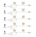
OK, if the zero crossing thing isn't a critical requirement, how about the idea of bypassing a volume IC as shown in attached diagram? Step 0 to 4 shows the sequence when volume is changed. "100%" means full volume without attenuation, "NEW" means the new volume after user has stopped changing volume. Would that be a stupid idea?
Attachments
Nice idea. Okay, the clicks when adjusting the volume have been eliminated. But is switch1 a relay? Then you have to manage the switchover again.
Ok, so how about using 2 relays in parallel and switch them from the MCU in a timing sequence so that the signal gets handed over without a gap...? Or even use a MOSFET to bypass the volume IC?
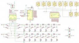
OK, I ordered PCBs with the attached schematic, let's see if that works well. I used 6 stages of relay attenuation, for volume outside the range I could always use the chip attenuator, but I think 6 stages should suffice. I am not sure if I need the bypass relays in parallel, but since they do not hurt, so why not I thought. Sorry for being OT, maybe I will start a new thread if the project goes well...
Attachments
I ran into the same problem of pops in the audio with a relay based attentuator and found the problem was acute when switching 7 relays off and 1 (MSB) on, going from 01111111 to 10000000. I was doing the switching with discrete digital logic circuits so the relays were changing in microseconds. I ended up using an Arduino processor to control the relays so I could introduce a 2 to 3 millisecond delay switching each relay sequentially, LSB to MSB turning the volume up and MSB to LSB turning the volume down. I least that is how I remember it, been a while. You can find my thread for the volume control in this forum. https://www.diyaudio.com/community/...input-mute-remote.326029/page-28#post-7272132
Switch all those positions going to zero without delay and all positions to one after 4 to 5 msec delay.
So fom 0111111 to 1000000 goes first to 0000000 and after 4 msec to 1000000.
Hans
So fom 0111111 to 1000000 goes first to 0000000 and after 4 msec to 1000000.
Hans
You must first measure the relay delay with an oscilloscope. This goes from about 1ms to 10ms, depending on the relay quality, temperature, coil voltage, etc. The software must take this into account.
- Home
- Source & Line
- Analog Line Level
- Relay volume control + analog switch with zero crossing