Yes, working with excellent SQ, fixed the BIII DC offset, AVC sounds also excellent with DSD & PCM.
All well then
Need help
Salas,
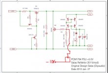
I was having trouble getting this build completed. I am using 9VAC Rcore transformer to power it. Initially the LED's were oriented in wrong direction. They did not glow but I was getting close to 6V. When changing direction of LED's, I noticed one of the LED's was not working. I replaced that and targeting to get 7V DC (3 green LED's). R1 = 2 ohms for 100mA current capability.
Now, even after changing LED direction, it wont light up. I changed the JFET also, just to be sure and am using 47 ohms RR value. Now, I get close to 11.3V on the output, which seems like the actual DC after rectification. Can you guide me what may be the issue? I am not sure if it is Q5/M1 or Q1-Q4 that is the issue?
Is there a chart showing expected internal voltages (when using 3 green LED's) to be able to debug which component may be problem? Even LTspice netlist will help simulate and debug. TIA
P.S: Initially, I was testing with 20ohm load but later realized that this load draws 350mA where as with 2 ohms R1 value, it will support upto 100mA. As of now, I am using 100ohms 5W load resistor.
Salas,
I was having trouble getting this build completed. I am using 9VAC Rcore transformer to power it. Initially the LED's were oriented in wrong direction. They did not glow but I was getting close to 6V. When changing direction of LED's, I noticed one of the LED's was not working. I replaced that and targeting to get 7V DC (3 green LED's). R1 = 2 ohms for 100mA current capability.
Now, even after changing LED direction, it wont light up. I changed the JFET also, just to be sure and am using 47 ohms RR value. Now, I get close to 11.3V on the output, which seems like the actual DC after rectification. Can you guide me what may be the issue? I am not sure if it is Q5/M1 or Q1-Q4 that is the issue?
Is there a chart showing expected internal voltages (when using 3 green LED's) to be able to debug which component may be problem? Even LTspice netlist will help simulate and debug. TIA
P.S: Initially, I was testing with 20ohm load but later realized that this load draws 350mA where as with 2 ohms R1 value, it will support upto 100mA. As of now, I am using 100ohms 5W load resistor.
Last edited:
Get Vbe readings from the current mirror Q1-Q4 transistors first. All should be reading 0.6-0.7V between their B-E pins. Get Vgs reading from M2. About 1.8V G-S is expected. For M1 4-5V is expected. Measure across R1. A 0.6V is expected on R1 from Q5. 100-300mV across RR says J1 is alright and pulling 2-3mA to bias Q5. If something from the above is way off then the relative semiconductor must be broken or wrong.
Salas,
Thats correct, it was Q3 which was broken. Fixed it and it works. Thanks for your help.
Regards
Thats correct, it was Q3 which was broken. Fixed it and it works. Thanks for your help.
Regards
Get Vbe readings from the current mirror Q1-Q4 transistors first. All should be reading 0.6-0.7V between their B-E pins. Get Vgs reading from M2. About 1.8V G-S is expected. For M1 4-5V is expected. Measure across R1. A 0.6V is expected on R1 from Q5. 100-300mV across RR says J1 is alright and pulling 2-3mA to bias Q5. If something from the above is way off then the relative semiconductor must be broken or wrong.
Hi Salas,
I bought last year 3 Reflektor PSU, and should have paid more attention as I needed 2 of them to deliver 12v......
I should have asked for 2 BIB.
Well, I got them now. Either I spare them for a future unidentified project or I try to use them on the current one.
So here I am. Is it possible with little mod to get them deliver 12v or is that too far away from 7v and mods would make it a completely different scheme ?
Don't want to bother you with that but I would be glad if it was a not too difficult path.
Thanks
Laurent
You could use a 9V Zerner and one red LED. The Zener in opposite cathode orientation to how a LED's cathode would normally be in LED1's place. The red in LED2 place normally oriented. For RX/J/D put a jumper.
Don't spare more than 150mA extra current and use 15VAC transformer. If you need dual polarity configuration there is a how to do floating dual polarity scheme out of two positives in the guide at its end. You would need a dual secondaries four wires transformer for doing that.
Don't spare more than 150mA extra current and use 15VAC transformer. If you need dual polarity configuration there is a how to do floating dual polarity scheme out of two positives in the guide at its end. You would need a dual secondaries four wires transformer for doing that.
You could use a 9V Zerner and one red LED. The Zener in opposite cathode orientation to how a LED's cathode would normally be in LED1's place. The red in LED2 place normally oriented. For RX/J/D put a jumper.
Thank you Salas for the tip.
What effect on noise using a zener instead of a combination of leds ? 😕
Laurent
About 6dB more noise but because of the 1000uF filter capacitor those differences are swimming at the bottom of the barrel.
salas what is that the Reflektor D will do that your SSLV Bib cant? In the sense what is soo unique about using the reflektor.
Its not a matter of can't do, they are simply different circuits. I have designed one evaluating on analog and the other on digital. Bib is much wider configurable and applicable, so it takes more involvement, Ref-D is focused in low voltage.
salas if you look at the voltage ref given to the gates of the mosfets even the best led cant go lower than 0.3micro Volts of noise so how is the regulator showing the noise in the order of 30nanoV?
The current value of 100uf is quite sufficient? or increasing it has got benefits?Large Vref C filter, no Vref amplification by the circut
Is there any way to run two Reflektor-D regs off a bipolar DC supply with a common ground reference (-/gnd/+)? In particular, I'm planning on running two regs off the +/-10VDC reg output of a DCB1 to get to +/-4VDC.
Is there any way to run two Reflektor-D regs off a bipolar DC supply with a common ground reference (-/gnd/+)? In particular, I'm planning on running two regs off the +/-10VDC reg output of a DCB1 to get to +/-4VDC.
They can certainly stack up like batteries with mid point reference
hi,
would it be possible to add a jfet ccs like this and raise the value of "560 yam" resistors a bit, so to lower output impedance, or is it just asking for instability/trouble?
would it be possible to add a jfet ccs like this and raise the value of "560 yam" resistors a bit, so to lower output impedance, or is it just asking for instability/trouble?
Attachments
Last edited:
There is the JFET instead of resistor option practiced already. You just replace the 1K with the JFET. No need for -V since any up to 1V Vgs(off) part sees enough VDS to ground by M2 with the standard low threshold type in REF-D. In the IRF640 occasion up to 2V Vgs(off) JFET will work fine.
Do you have drawings or some other description of the Ref-d mini ?
I like the idea of the Reflektor-D Mini. I wonder if it might be nice to have a separate little PCB to hold the AC input stuff, connectors, rectifiers, big filter cap (maybe even provisions for those 4pole Mundorf Rolls-Royce guys?).
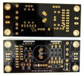
Finally the Reflektor-D Mini is ready and the description pdf is attached.
A little raw DC companion board that can use common two pole reservoir capacitor as well as Mundorf four pole -without any modifications needed- is ready too. I have named it DC Flexy 🙂
Read it to tell me if its understandable text or you need some clarifications. BTW the PCBs print is not very nice yet because they are just test boards.
Attachments

- Home
- Amplifiers
- Power Supplies
- Reflektor-D builds