PW8888
I have tested that 1.7V DCin-DCout is absolutely no go area bcs that is where the CCS really knees down and lets some ripple pass. It will goof current setting from 2V dif point though. So you will need at least 3V higher raw DC than DCout in worse low mains hours case. A 9VAC Tx will give about 11V raw DC for instance because diodes Vf loss is a serious % in this region of voltages so make your plans accordingly. Maybe a 6.3VAC Tx for tube heaters will suite your 3.3V one. You will skip some heat in the box, but the Ref-D itself will not have a problem with 9VAC and the CCS will run bit better.
It will generate less heat yes. But you will have to watch that in all circumstances the rectified DC RMS voltage stays at 3V higher than the regulated output voltage you set. 2V is the hard limit. The input MOSFET's circuitry has to be contained you see. Under 3V difference the CCS will be losing PSRR until about 1.7V difference when rectification ripple will start passing it through. 2.8V is the lowest output voltage you may set while retaining the regulator's impedance correct by the way.Hi Salas
I build 6 of them with success. Very very good
I have one question
I ONLY use them to generate 5volt or less...
Is that possible to use a 6VAC transformer instead of 9 VAC...
I would generate less heat i suppose ?
Thanks
Phil
P.S. Review if your current settings could have been tighter with no current limit danger still. Six? In what kind of application, had different regs before?
Thabks for all those very clear info !
I am using them with SDtrans / sync dac 9018D
I ve been triing the sdtrand with the acko powersupply has well... Refelktor seems better..(need to reconfirm)
I would like to find a way to change the cooling system for all 6 modules
I have 9vAC transformer at the moment...
I must have 65degreeC at the moment...
A little bit too much...
6VAC Tx would work with enough margin for 3.3V regulators. For 5V regulators 7VAC would be more secure unless you substitute for Schottky rectification diodes and lose less voltage there. Then 6VAC would suffice too. You can extend with short cables and mount MOSFETS down on some big flat cooling surface. But electrically isolated with Silpads and plastic grommets.
6VAC Tx would work with enough margin for 3.3V regulators. For 5V regulators 7VAC would be more secure unless you substitute for Schottky rectification diodes and lose less voltage there. Then 6VAC would suffice too. You can extend with short cables and mount MOSFETS down on some big flat cooling surface. But electrically isolated with Silpads and plastic grommets.
As far as Schottkies I found Cree SiC sounding best especially in hights e.g.: C3D04060A. Also powering left and right channels speartelly (AVDDs) of the dac chip brings benefits in terms of sound stage and blacker background.
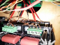
Wiring
I removed the single wire runs to the legato and made jumpers. I use 2 15 volt+ and - ps, so 4 total. This way of wiring defeats the sense function but sounds more dynamic and open. Did the same with the reflector powering the Buffalo III. More direct and punchy. Didn't expect any real change due to wires were only about 5 cm long.
I removed the single wire runs to the legato and made jumpers. I use 2 15 volt+ and - ps, so 4 total. This way of wiring defeats the sense function but sounds more dynamic and open. Did the same with the reflector powering the Buffalo III. More direct and punchy. Didn't expect any real change due to wires were only about 5 cm long.
Attachments
Biker,
mechanically fix the copper joints before soldering.
i.e. bend the solid core end around the copper loop and crimp it up so that you have a copper to copper mechanical joint.
Then solder.
mechanically fix the copper joints before soldering.
i.e. bend the solid core end around the copper loop and crimp it up so that you have a copper to copper mechanical joint.
Then solder.
I removed the single wire runs to the legato and made jumpers. I use 2 15 volt+ and - ps, so 4 total. This way of wiring defeats the sense function but sounds more dynamic and open. Did the same with the reflector powering the Buffalo III. More direct and punchy. Didn't expect any real change due to wires were only about 5 cm long.
Salas,what is the technical explanation for this difference on the sound reproduction.
Salas,what is the technical explanation for this difference on the sound reproduction.
If the sensing isn't representing the real consumption nodes with what is sees at the client board's power connector it may well be better to just go nearest possible with heavy wire and bridge the sense at the reg's connector. No info is better than wrong info.😉
but what can distort-interfere the real consumption nodes,the noise and or poor implementation?
Say the client PCB has various consumption points for ICs etc. along a long thin lane that ends up to some power-in connector or pad. And a general ground plane. No star connection for anything. Some blending goes on along the power line's intermediate track resistances. Plus presenting a ground point which is general and about. If the reg senses an undefined situation for its reference then its no better off than sensing closely to its own output to at least keep shortest antenna area to possible noises. Check both methods i.e. two wire and four wire when in doubt. Distance, wiring style, and load PCB peculiarities will maybe show you enough subjective differences on what to prefer. Possibly visible on a scope as least power line interference as well.
Hi Salas,
how much ac voltage (input) should i planed when i want an output from 3.3V (for my Lucian WaveIO and Soekris DAC)?
Want to order a custom made transformer for my project.
Thanks
how much ac voltage (input) should i planed when i want an output from 3.3V (for my Lucian WaveIO and Soekris DAC)?
Want to order a custom made transformer for my project.
Thanks
Hi Salas,
how much ac voltage (input) should i planed when i want an output from 3.3V (for my Lucian WaveIO and Soekris DAC)?
Want to order a custom made transformer for my project.
Thanks
9VAC transformer secondary.

Hi all,
i found here a 9VAC transformer and build the regulator. 🙂
With the dummy load (20R/5W) i got 5V (2 x green LED, jumper on RX, R1 = 1R) and it seems to be all ok. But when ich connect the WaveIO (5V / 0.5A) then the voltage drops down to 4.4V. What is going wrong?
Pleas help, thanks!
i found here a 9VAC transformer and build the regulator. 🙂
With the dummy load (20R/5W) i got 5V (2 x green LED, jumper on RX, R1 = 1R) and it seems to be all ok. But when ich connect the WaveIO (5V / 0.5A) then the voltage drops down to 4.4V. What is going wrong?
Pleas help, thanks!
Measure first what the client board draws using a 7805 or other non restricted 5V source with a 0.1 Ohm resistor in between to derive current = V/0.1 from resistor voltage drop or the DMM in series current mode. Watch peak current for a while. It can even be oscillation. If the max current it takes is bellow 600mA then use two wire output mode by jumpering 0S to 0F and S+ to F+ locally at the reg's output connector to see if it continues dropping. If the load demand is truly more than 600mA, then its normal to drop output, its limiting and you would need a lower value Rset. ICCS=0,61V/Rset.
- Home
- Amplifiers
- Power Supplies
- Reflektor-D builds