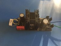
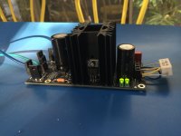
Thanks 😉
I'm going to try Mundorf M-Lytic also.
🙂 quite tricky to adjust salas board for it.
Salas: is there any theoretical technical problem with using a cap with long leads (big film caps as mentioned here) for C1? I have actually been using a Panasonic PPS SMD cap with good results.
Really liking Panasonic polymer 1000uF 16V for the Vref filter cap as well (better than Silmic II for me).
Powering a B-II DAC board, and another RefleKtor powering my Ethernet-I2S board.
Really liking Panasonic polymer 1000uF 16V for the Vref filter cap as well (better than Silmic II for me).
Powering a B-II DAC board, and another RefleKtor powering my Ethernet-I2S board.
Longer leads mean more lead inductance, so with a no leads or minimum leads capacitor you gain some better behavior in that department because of form factor. In the greater scheme of things there are pcb tracks involved also that can ameliorate the total differences.
Hi Salas,
will you share, please, how to modify Vref to have 8V out with around 200-250 mA. What secondary for transformer in this case?
will you share, please, how to modify Vref to have 8V out with around 200-250 mA. What secondary for transformer in this case?
12V secondary. One LM329 instead of an Led. Cathode orientation opposite to if it was an Led. Its third leg is not connected inside the TO-92 case, so bend it over or cut it out. Second Led and Rjx positions use jumpers. It may show 8V or over 8V depending on LM329 sample, but not less than 8V no more than 8.32V. Current setting as usual in the manual.
Hello!
I think I can post this question here, but Salas, if you find it inappropriate, I apologise, please erase the comment.
I intend to use some of the Reflektors just with a 0,1cap as an upgrade, but for some dac boards that have a lot more potential, I want to make radical upgrades. I know it looks insane to use 20us dol resistors, but I can't resist, just a few...
Questions :
- I want to install a 4pole mundorf GPLUS cap.
(AG+070) - 10000uF 80V Mundorf MLytic AG+ Electrolytic Capacitor | Hifi Collective
Can someone tell what are the 4 points where I should solder it? Please refer to the image in the Reflektor build guide, there is an image of the board without parts, and the holes are referenced.
- I want to install Charcroft Z-Foil Resistors in R1 and R6.
It can be bought here,
0.4W Charcroft Z-Foil Resistors | Hifi Collective
Can someone tell, send a link of the right resistors for R1 and R6?
Many thanks!
You can use (CAR-250) - 1K 0.4W Charcroft Z-Foil Resistor | Hifi Collective but out of stock
I have ordered this Y07061K00000T9L - VISHAY FOIL RESISTORS / VPG - Résistance traversante à film métallique, Série VAR, 1 kohm, 400 mW, ± 0.01%, 200 V, Radial | Farnell element14 in place
For R1 you can use 5W Mills Resistors MRA05 | Hifi Collective
TioFrancotirador established MLytic,apparently he drilling 2 hole additional😛 it might give you more details.
Hi clsidxxl
Yes, for R1 I'll use Mills, not VARS.
I guess that's the one :
(MRA05-115) - 2R 5W MRA05 Mills Resistor Right?
Can't find
"R5 = 1 Ohm 1/4W or 0.5W 100ppm or better, axial metal film"
not in hifi collective, not in any of the other sites I'm used to buy.
I think it's possible to find some points on the board where the 4pole cap can be soldered - not directly, of course, some wires must be added...
Thanks!
Last edited:
Last edited:
Nice pics. What is it to work for?
In preparation for Ian's FIFO re-clocking system 🙂 Other R-D will also be for the Ian's FIFO, for the clock board section 😀
Also have a couple of your BiB's in readiness for Soekris R2R (one day)...
Soekris
Hi aive,
Please share your soekris project, if it is related to R_D psu, of course, when it's ready!
Good diying
Hi aive,
Please share your soekris project, if it is related to R_D psu, of course, when it's ready!
Good diying
Have you drilled holes in the PCB to allow cooling air to pass up into the internal "chimneys"?Finally put together one of the two kits I bought over a year ago. Such an elegant design, thanks so much Salas and Tea-bag!
Tea-bag, those component kits were awesome. Made everything so simple, can't believe you also measured Idss!! So great 🙂
View attachment 492228
View attachment 492229
It has two such holes already (near R3 & R4). Maybe aive can take a bird's eye view shot of the build and they will be visible down the chimney.
Its good to also have ventilation holes on top and bottom lids of a box if its not that spacious and the current setting is high. At least in areas immediately above and below the sinking towers.
Its good to also have ventilation holes on top and bottom lids of a box if its not that spacious and the current setting is high. At least in areas immediately above and below the sinking towers.
Today I received the 1K VARS resistors.
I installed one in R6 for amanero reflektor and other in R6 for reflek to dac.
The improvement is incredible, much less metalic, much more colors, even details, very sweet, musical.
I am waiting for more VARS. One 62 R VARS will be installed in the 3.3volts reflek, for amanero in the place of 62R, just after the green leds, Rx/J/D. These VARS are magic.
Next will be true copper 0.1uf, etc, one part each time. I will report the results each time I insert one component. Thanks TioFrancotirador, I am following your tips.
"Three green LEDS on LED1-LED2 and Rx/J/D positions give near 7V.
Two green LEDS on LED1-LED2 positions and a jumper on Rx/J/D position give near 5V."
Means that a green led makes 2volts... but I can be missing something here...
What value for a resistor can make 2 volts? What value for a resistor to replace one green led? Thanks.
This would be for the reflek that has 5 volts. It has not yet a VARS in voltage set.
The 3.3volt R-D will have a VARS in the place of 62R.
I am now trying to figure out the value of the VARS to install in the 5volts R-D...
I know that there are some newbies like me!
Salas, can you please help?
Do you agree that a VARS in the voltage set will make such an important difference as in R6?
Last edited:
R6 has extra 5mm pads for VAR also because it has been tried in past experiments and deemed worthy. Other positions are less interesting technically for VAR, but find for yourself.
Not all green LEDS have the same Vf. Measure yours with battery and resistor as described in the pdf manual. Its not a very good idea to replace an LED with a resistor because its easier to be drifting. In any case V=I*R and I=2mA. So you calculate what you want to test.
Not all green LEDS have the same Vf. Measure yours with battery and resistor as described in the pdf manual. Its not a very good idea to replace an LED with a resistor because its easier to be drifting. In any case V=I*R and I=2mA. So you calculate what you want to test.
- Home
- Amplifiers
- Power Supplies
- Reflektor-D builds

