Tighter if you need it. Less open loop bandwidth though. Boosts the Zo and linearity spec but with an extra active element that has its own speed limit and noise thing to share too. Its drastic though and effective as many much complex and voltage eating mirror schemes. Its a matter of system synergy and/or taste. You can also try low noise pin compatible alternative transistors and Jfets that fit the board if curious. As you do with passive parts.Salas,I do not doubt you did the best with Reflektor design,it is a superb board.
What is the change in sound when swap K117GR Instead R6.
Hi,
I have just tired K117GR in position of R6 and I must say I am impressed. Sound is more firm, tight and heavier. I like it. This mod is definitely worth applying.
Just the voltage increased around 0,3V in my case, so some leds adjustment is needed to achieve same/needed output voltage.
Thanks Salas.
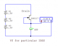
If Vout value has to be exact, particular K117GR IDSS better be known and Vref elements tested for Vf at such a current. Because that IDSS is reflected to the Vref. Its a Reflektor, what else we would expect?😀
If Vout value has to be exact, particular K117GR IDSS better be known and Vref elements tested for Vf at such a current. Because that IDSS is reflected to the Vref. Its a Reflektor, what else we would expect?😀
Well, I expected Vout to drift a little. However in my case it does not matter that much. AVDD of ak4490 chip accepts anything from 4,75 to 7,2V. So I just had to make sure it is below the max(7,2V). Just replaced one of three green leds with red one.
Anyways I want to go further with mode, so do you have any words on replacement four 2N4403 with two BCV62C for current mirror?
And second, I see on some of those Japanes drawings that they skip C2. Is it ok to try it out on your current Ref-D design?
OK. But if someone must be exact, either a Vf test on the real board with dummy loading and LED sockets, or a test before assembly of R6=Jfet and candidate LEDS is easy to perform.
As for alternative single die SMT BJTs keep in mind that BCV62C has 10dB NF when 2N4403 is genuinely low noise and you can still tie Q1 & Q2 together. Q3 and Q4 run different mW.
Skipping C2 will skyrocket the noise especially 1/F. But it won't break something. Kazuo used many Ref-D perfboad variations in many of his subsystems for some synergy. I suggest you arrive to yours on a small protoboard too if excited for mods and various tastes before finalizing anything on the real PCB.
Attachments
OK. But if someone must be exact, either a Vf test on the real board with dummy loading and LED sockets, or a test before assembly of R6=Jfet and candidate LEDS is easy to perform.
As for alternative single die SMT BJTs keep in mind that BCV62C has 10dB NF when 2N4403 is genuinely low noise and you can still tie Q1 & Q2 together. Q3 and Q4 run different mW.
Skipping C2 will skyrocket the noise especially 1/F. But it won't break something. Kazuo used many Ref-D perfboad variations in many of his subsystems for some synergy. I suggest you arrive to yours on a small protoboard too if excited for mods and various tastes before finalizing anything on the real PCB.
Thanks Salas for tips.
I will try BCV62C just for curiosity sake and see how it sounds.
Tips for K117GR and LEDs adjustment will be also handy once I get to my next build: dual symmetrical Ref-D -/+5V for pcm1704, where I will have to be more precise.
Last edited:
I've built the 4 reflectors I needed to power my DCX2496 crossover and then MAGIC came out of my speakers. The new power supply made a HUGE difference. Won't show you pic's just yet because it's a really messy rat's nest of wires in this testing stage.
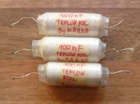
Inspired by the tweaking here I ordered some Russian old stock Teflon insulated Al foil capacitors for C1. They need some tweaking as they are encased in an iron can and have magnetic output leads. After they are freed from their "prison" they should do magic especially considering they're worth only a few bucks.
What's your favorite way of supplying the Reflectors?
I've got 4 reflectors to power, drawing around 3A current. Right now I'm powering them with 3 12V 1.5A switchers and to my ear the circuit seems to work fine.
For a final sollution I'm considering two options:
I have two 50VA 12V transfo's for halogen lighting and could make a nice CRCRC filter or LM317 after the rectifier to bring the volts to a lower value.
(What is the minimum input voltage for 5V out?)
Or I could use a 12V 6A SMPS and eliminate AC inside the chassis and still use CRC filtering to bring the voltage down a bit.
Any thoughts about this?
Tnx,
Marko
PS. Salas, you made a great job designing the Reflektor
Hi, thanks.
5V more input than Ref-D Vout is enough. Even more is better if you got the heat exchange capacity.
Linear pre regs and/or passive filtering is usually better but if you can't see any switching hash when scoping the SMPS after filtering it with CRC, then its acceptable too.
5V more input than Ref-D Vout is enough. Even more is better if you got the heat exchange capacity.
Linear pre regs and/or passive filtering is usually better but if you can't see any switching hash when scoping the SMPS after filtering it with CRC, then its acceptable too.
Hey Salas,
Since you claim two steps regulation is better than one in general. What kind of results we could expect when e.g.: Ref-D 7V would be fed with DC from SSVL 1.1 BIB running @ lets say 12V? Does such extreme configuration make sense?
Since you claim two steps regulation is better than one in general. What kind of results we could expect when e.g.: Ref-D 7V would be fed with DC from SSVL 1.1 BIB running @ lets say 12V? Does such extreme configuration make sense?
Last edited:
Marko already has a multiple regs situation based on high total current DC feeds. So the talk was about heat efficiency VS good filtering or the linear way.Hey Salas,
Since you claim two steps regulation is better than one in general. What kind of results we could expect when e.g.: Ref-D 7V would be fed with DC from SSVL 1.1 BIB running @ lets say 12V? Does such extreme configuration make sense?
Separate Tx and own rectification like in your situation fully populated REF-D PCB still has isolation benefits. If you want to try externally rectified and stabilized individual DC line for connoisseur sonic reasons, I don't know what will play better between simple CLC passive or some pre-reg of choice because I haven't compared. In case of BIB----> REF-D test you must ensure higher BIB CCS setting than in the REF-D. Lot of heat using those two shunts together in other words.
Yesterday I rewired the power supply, increased the 0F+ wires crossection to 0.5 mm2 and connected a balanced microphone cable as 0S+. That didn't play well. The voltage dropped on all regs by some ammount and the DCX wouldn't even start. Took out the regs and tested each with a resistor - everything perfect. Put them back in - nada...
Then I diched the microphone cable and wired the 0S+ directly at the reg. terminals, and this time the voltages were OK.
What's the deal with that?
The mic cable's two wires are rather thin... The shields were connected to the star ground and disconnected at the regs.
Thank you for your patience Salas.
Ps.
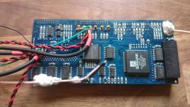
Here's the board, I'm not particularly proud of what I've done but i managed not to kill anything. And the now custom russian Al foil teflon capacitors.
Then I diched the microphone cable and wired the 0S+ directly at the reg. terminals, and this time the voltages were OK.
What's the deal with that?
The mic cable's two wires are rather thin... The shields were connected to the star ground and disconnected at the regs.
Thank you for your patience Salas.
Ps.
Here's the board, I'm not particularly proud of what I've done but i managed not to kill anything. And the now custom russian Al foil teflon capacitors.
Attachments
The deal with that was probably oscillation. Can be something disruptive in the full complex scheme. It takes an oscilloscope and elimination of various conditions until to know. Maybe those little ceramics, some interaction of all those supplies power nodes reference, go figure. Rather not worthy to debug if it will prove too complex when the result is still good with two wires only. Can have thick gauge and maybe R6=JFET also so to keep Zo low enough in the absence of four wires if can't have the regs right next to the load. But keep them as practically closest. Those naked Teflons are good.
The thing is I had it working before I changed to mic cable. I changed the grounding scheme a bit from the last time but it was such a mess then that I can't recall the exact details. I think it's worth a few trial an error attemts before calling it a day. The way it works now with two wires is more than good so it's not worth to spend too much time debugging.
I'm going with the 12v SMPS brick to supply the power, much less heat and bulk in the chassis.
Now a general question about HF decoupling. I'll use either CRC with 2V drop at the R or CRCRC with 1V drop at each R. What capacitors to use? Since I'm not smoothing the DC but only the higher frequencies I say I'd use 10 uF tantal || 100nF ceramic for each stage but only because I don't know better. How about using the same capacitor combination in the Cd position?
Try CAT-5 twisted S pairs too in case there is some cable parameter combining with something on the DCX.
Its OK to use same decoupler combo in the Cd too.
Its OK to use same decoupler combo in the Cd too.
It was a tough few days for me, my amp went in oscillation mode and self-destructed after a speaker cable change and I managed to kill the DCX too. Ugh.
So for now no progress until I get another DCX.
After I installed the new clock and glued the coax cable, the glue failed to hold on to the teflon insulation on the coax and the cable teared the traces it was soldered to. I managed to track and repair the traces, they passed the continuity test but the DCX failed to start after that. I also had issues with oscillations and grounding. I have to carefully rethink the whole project.
Bad news. Wishing you better luck from now on.
Is it a wide bandwidth power amp with no series output coil? Are the speakers alright at least?
Could there be further layers meeting in the pad that the cable pulled out?
Is it a wide bandwidth power amp with no series output coil? Are the speakers alright at least?
Could there be further layers meeting in the pad that the cable pulled out?
Salas,
I see C2 1000uf has huge impact on sound signature. Polymers are more precise, but less natural. Elna Silmic II is very natural, more body, but not so precise. I wanted to get Black Gates, but the only ones at reasonable price I found are 2200uF/16V. Is such capacitance and voltage ok for C2 position on Ref-D@7V?
Thanks
Its OK if getting slower to charge up for building to the nominal Vo is no problem for the client electronics to miss a startup or something timing wise as you flip the power on switch.
Its OK if getting slower to charge up for building to the nominal Vo is no problem for the client electronics to miss a startup or something timing wise as you flip the power on switch.
Thanks, Salas.
Seems like it is ok in my case.
Docs for ak4495 states that: "The power up sequence between AVDD, VDDL/R and DVDD is not critical."
I actually forgot once to connect my Ref-D to analog section of chip (only digital section was powered). I was thinking I did something wrong elsewhere, when I heard no music 🙂. Fortunately I did not do any harm to Ref-D nor to the ak4495 chip. So 2200uf hopefully will be ok then.
Thanks!
- Home
- Amplifiers
- Power Supplies
- Reflektor-D builds