-1/4W is OK. 53mW dissipation at 5V.
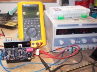
-Catching the startup ramp with single shot in long horizontal scale.
-Some ARM startup common pattern, probably
-Catching the startup ramp with single shot in long horizontal scale.
-Some ARM startup common pattern, probably
Added the resistor and it has improved. It now seems to not come on when the dac is off for a long time. In this situation it still does not come on, BUT, it seems to reliably come on after repeated turning off and on. So it seems to only fail once at the beginning. I only tested about three or four times over the last day, I'll test some more.1/4W is OK. 53mW dissipation at 5V.
Have not done this but read in beaglebone forums that ramp up seems to play a role, with the boards not starting up consistently if the ps has a slow ramp up.Catching the startup ramp with single shot in long horizontal scale.
I want to use the reflektor, is nice sounding and compact. Maybe I'll add an led to the front panel that is turned on by the bbb as soon as it's booted, that way I'll know to hit the on/off switch again if the bbb led does not light up in 20 seconds or so. I think this is easier than the relay with the delay if it consistently comes on after the initial fail to start?
Thanks again Salas.
Hmm since the resistor helped matters, another one in parallel can tell us if there is further room for improvement. Relatively slow ramp up with no overshoot is considered a safety feature when powering digital chips in general. Maybe smaller CM in your case. So it charges up faster. Yes, since the resistor solved half of the issue, the LED reminder sounds like a good idea.
hi,
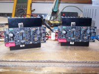
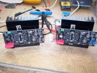
Just finished two reflector builds for a shiga2 build.
Rectifiers and smoothing caps will be offboard in seperate psu box.
Nice and stable voltage, perhaps a bit to high one at 5.07V and one at 5.1V, but i'll ajust to get it spot on.
got bigger hearsinks for better distribution of the heat inside case, barely gets warm to the touch @700mA.
Waiting for my rcore trannies (selectronics) and let the fun begin.
Very easy to build, about 1,5 hour each, heatsink beiing most of the work.
Thank you Salas!!
Attachments

Salas
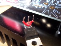
well my pin reversing works, you see something wrong with it?, if not i was the first to do it like that. If it is the wrong way, its not my idea.
Do you have a sugestion wat to put there perhaps?
Raw dc will be 2200uF regulator 1000uF, standard shiga ps.
Regards
John
well my pin reversing works, you see something wrong with it?, if not i was the first to do it like that. If it is the wrong way, its not my idea.
Do you have a sugestion wat to put there perhaps?
Raw dc will be 2200uF regulator 1000uF, standard shiga ps.
Regards
John
Last edited:
Its a nice way to reverse pins with underside connection so to keep cabling very short. Well done.
CD (decoupling capacitor) can be 100nF MKP. Its for the incoming DC wiring inductance not to trouble the CCS. Use the little holes. 5mm pitch or 15mm pitch from 0V to the other two (which are commonly connected to +Vin).
Vout drift down can be less mV than with board level small sinks. Wait for half an hour warming before judging the Vout you want to adjust anyway. If the application has a Vcc value tolerance, as they normally do, don't bother for 0.05 or 0.1V differences to nominal. Unless its fun to nail it.
Thanks Salas 
Where would you put a choke if desired? and is it better with a choke?
Can it be fitted on the board?, it does seem a lot cleaner. see postt 175 in this thread.
The shiga2 black boards supposed to be very critical when it comes to the right V in, they also have to pretty close, ill try to nail it a bit beter.
regard,
John
I would use Duncan PSU software to simulate the raw supply at hand and see what choke could fit in there. Including its RDC and the CCS draw as load. Some compact and cheap choke since it can do good to EMI filtering mainly but its not really necessary.
well... duncan psu software and I don't see eye to eye, we always argue.
never mind, if you say not neccasary i guess it's not needed here.
regards,
John
never mind, if you say not neccasary i guess it's not needed here.
regards,
John
Hi,
I just put 0,1uF CuTF V-CAP (teflon) for C1. OMFG!
Another proof of how important is power supply to analog dac section of your dac chip and another proof that your audio signal is mainly as good as the power its created from. Another part that brings Salas Reflector D to another level. Thanks Salas!
It replaced already good 0,1uF ClarityCap MR that I had in my build.
It is not even burned in well yet but if I were to describe impact on sound it would be: more liquid, wider bandwidth (especially heights), bass is more firm. It is just better in every aspect: transparency, clarity, musicality. Now it seems like notes sound/last longer, more natural/organic.
Now my question is:
The cap has to leads red and green. The green lead indicates the outermost foil and as documentation states: it should be connected to the lowest impedance path to ground.
Now in my build I connected green lead to F+ and red one to R5 resistor. Is that correct according to documentation? or it should be connected the other way round?
Please let me know your opinion. Thanks.
Last edited:
Very nice! I received two more Reflektors and will install SCR top of the line teflon's...
it changes everything.
I removed the ampom XE XAL AL 0,01uf cps that were soldered in parallel with the 0,1uf wima. The sound was very poor, when you get used to the ampom; I'll report the results with the SCR caps on it, not in parallel, just 0,1caps instead the wima. CuTF V-CAP are soooo expensive...!
Now my question is:
The cap has to leads red and green. The green lead indicates the outermost foil and as documentation states: it should be connected to the lowest impedance path to ground.
Now in my build I connected green lead to F+ and red one to R5 resistor. Is that correct according to documentation? or it should be connected the other way round?
Please let me know your opinion. Thanks.
The Reflektor-D has no output capacitor storage. All there is to it is that little values RC termination Zobel (R5-C1). Ground side is F0 of course. C1 is connected between R5 and F0 in the manual's schematic.
My fault. Green lead is obviously connected to F0. So it seems I am good. Thanks again Salas. Cheers.
BTW Has anyone compared Teflon copper vs silver mica in place of C1? Or maybe there is something better than that? Teflon silver foil?
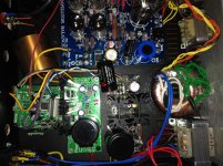
TioFrancotirador you can show your Reflektor with the V-CAP please🙂
Sure. My dac is constant build in progress 🙂
An externally hosted image should be here but it was not working when we last tested it.
Attachments
Thank🙂Nice.
What is CM cap.,Mundorf?
Mundorf M-Lytic AG+ 4 pin 10000uf. Really good one.
I also use:
Vishay VAR 1K at R6. Others resistors are Takman metal films.
1000uf is Elna Silmic II
R1 is Mills MRA05
4x8TQ100 Schottkies
- Home
- Amplifiers
- Power Supplies
- Reflektor-D builds