The sinks aren't pre-grounded to save insulation hassle and enhance heat transfer. Its better to have option than not. Normally it isn't a problem. Try to see if influential in your case. Nice to know you like the sonic results.
You may tune up Vout by taking advantage of the Rx/J/D position. Say by leaving in the LEDs you now got and add some Rx value. Or replace them with lower Vf LEDs and add a diode. Whatever suits you. Don't do such experiments with the real load connected. Use a dummy load, tune your Vref section parts for target Vout well and steady, reconnect when sure. Not to kill chips with some overvoltage set up mistake.
At the moment I have two green LEDs installed. Could I use a trimmer for Rx?
Do I need to have 7V and a trimmer to get 5.5V or just add it to the 5V I already have (two green LEDs)?
Sorry for all those questions. I am definitely not a pro! 😉
Do I need to have 7V and a trimmer to get 5.5V or just add it to the 5V I already have (two green LEDs)?
Sorry for all those questions. I am definitely not a pro! 😉
On the Rx pads female socket pins can be installed to easily try various resistors. To go from your 5V base up. If for 2mA nominal current in the Vref expect 0.2V additional Vout per 100Ω. If using the JFET mod probably more mA will be produced and more mV/Ω.
Yes, you could use a trimmer instead to home in. Must be arranged as a rheostat though (one of its outside pins joined to the middle pin). Plus its not easy to connect it and use it there due to its shape and pins arrangement. Maybe with small wires. Still better to be replaced with a standard resistor of near value after removing the trimmer and measuring its set value.
Yes, you could use a trimmer instead to home in. Must be arranged as a rheostat though (one of its outside pins joined to the middle pin). Plus its not easy to connect it and use it there due to its shape and pins arrangement. Maybe with small wires. Still better to be replaced with a standard resistor of near value after removing the trimmer and measuring its set value.
I'll try the female sockets with resistors first. Is there information about the JFET mod in this thread? (can't find it in the manual)
Its about replacing the R6 resistor with a JFET as an active current source. Gives an alternative technical and subjective character to the reg. Yes there is information, characteristic posts with pictures are #149-156.
With the JFET in R6 the voltage has gone from 5.15v to 9.1V. How do I bring the voltage down to 5.5V?
Should I see if I can reduce further with one yellow led in 1, bridge in two and bridge in RxJD?
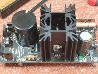
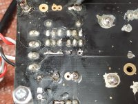
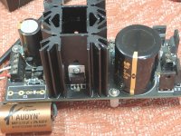
Here are some pics. Not exactly great soldering as Mundorf Silver Gold solder leaves a lot of residue which is difficult to clean.
Attachments
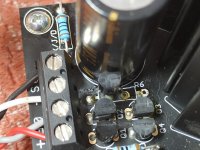
without the 100ohm resistor in Rx it's about 8+V.
It needs a jumper replacement when removing that resistor. What voltage can you measure across the 100Ω ? That will tell us the mA running in the Vref.
2N 4403 E19
This is a transistor not a JFET. That is why you got a wild Vout bump.
I do have some K170BL 1H if this is a better choice. I used the parts from the full kits.
K170BL can still work although bit forceful. Lets check if it looks genuine. Show us a close up picture of it before you use it.
- Home
- Amplifiers
- Power Supplies
- Reflektor-D builds