Hi Dimdim,
I have used this image as reference to connect to the DAC. https://hifiduino.files.wordpress.com/2015/01/spdif1-2-2.jpg
I`m using Amanero and do I need to use an external 3.3V for it? I guess its powered by USB itself?
1) Not powering the "dirty" side of the DAM I2S isolators, or
I have used +/-12V at PowIn PowGnd PowGnd PowIn for positive and negative supply. Is there anything else that needs to be powered up externally?
https://hifiduino.files.wordpress.com/2015/01/r2rconnect.png
2) Forgetting to connect GND to the "dirty" side.
the PowGnd is already connected internally on pcb on dirty side isnt it? Is there anything that Im missing in here?
Can you please post an image of which GND you are talking about. It will be really helpful. Thank you.
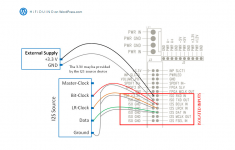
Looking at this picture:

The easiest thing to try is to connect J3's "ISO +3.3V" to the Amanero's 3.3V output pin (pin 9 as seen here):

The Amanero is fine being powered through USB.
The easiest thing to try is to connect J3's "ISO +3.3V" to the Amanero's 3.3V output pin (pin 9 as seen here):
The Amanero is fine being powered through USB.
I’ve got the new version 7 module and can see it only accepts dc.
However, the power input does not indicate which pwr input is for dc+ and which is for dc-. It only says pwr ground, ground, pwr.
The old version didn’t care due to ac input, but does the new version care, and which is which? Is closest to J1 input - or +?
Many thanks!
However, the power input does not indicate which pwr input is for dc+ and which is for dc-. It only says pwr ground, ground, pwr.
The old version didn’t care due to ac input, but does the new version care, and which is which? Is closest to J1 input - or +?
Many thanks!

Thanks Søren. I thought so too. I just didn’t want to risk frying the board.
So the new version has ac rectification too. I assume the DC preference is due to better sound -and perhaps less on-board capacitance since it relys on the main smoothing/reservoir caps being in the external power supply 👍
So the new version has ac rectification too. I assume the DC preference is due to better sound -and perhaps less on-board capacitance since it relys on the main smoothing/reservoir caps being in the external power supply 👍
Is it correct that the dam2941 cannot accept a master clock if using i2s input from an external FIFO? In the dam1121 manual I see it can take an LVDS master clock - is this board able to take a master clock over HDMI LVDS (if so can the 2941 too)?
Thank you.
Thank you.
Master clock for what ?? I2S just have Bit Clock, Word Clock and Audio Data.... The LVDS clock on the dam1121 is not a master clock, but for syncronous clocking of multiple dam1121s. That, and the internal clock, need to be controlled by a dam1121.
I see thank you. It would be if you wanted to use a separate FIFO with an external oscillator. What is the difference between the dam2941 and two dam1121s synchronized to run balanced? The input options on the 2941 or are there other differences?
The 2941 manual link doesn't work which is why I am asking (http://www.soekris.dk/download/dam1941/dam2941_manual.pdf).
Has anyone solved the loss of lock when using a physical volume pot...mostly happens when turning the volume down....
Rev7 on USB via Amanero.
Ta
WM
Rev7 on USB via Amanero.
Ta
WM
I assume the 2941 also feature all the "upgrade" from the rev7 1021 ?Please use the dam1941 manual for now, everything are the same....
It happened to me sometimes, when before I had the 1021 ver.4 card, but now that I have the 1021 ver.7 card it always happens to me that by decreasing the volume with the 10K potentiometer, the signal blocks and the music disappears, except reappear after several seconds. It happens less easily as you increase the volume. Why? Thanks for the reply
Good day!
Can anyone tell me what the purpose of the Volume going to +15 is? I assume 0dbfs is at setting 0? So the +15 is to compensate for recordings at low volume, where there is no clipping when the volume is set at eg +10?
I am using the DAMlite from DimDim to control the volume of the DAM1021. The SW is currently limited to control up to 0 volume only, so I need to change that before being able to try out.
Many thanks! Erik
If you want an unaltered PCM stream to hit your DAC, 0 dbfs is the setting you want (then there is still a ton of processing made to the signal - but still...) . In the same way as you can attenuate the output level by recalculating the PCM stream to represent a lower level, you can go in the other direction as well - the only requirement is that you have a spare bit to accommodate the higher PCM word value and that your analog output stage can handle the rised level. This is accommodate for in the DAM. See it as a possibility if your gain structure would require more gain. I use the added gain in one of my systems. IN an other I have it fixed to 0.
//
//
- Home
- Vendor's Bazaar
- Reference DAC Module - Discrete R-2R Sign Magnitude 24 bit 384 KHz