I have YO-02 USB to TTL adapter... ...So do someone have rev7 with USB to TTL issue fixed?
With proper adapter there is no issue with rev7 but you have to remember it's now shared interface so either by J3 or J10 can be actively used other stays readonly.
What that means shared and read only?With proper adapter there is no issue with rev7 but you have to remember it's now shared interface so either by J3 or J10 can be actively used other stays readonly.
I asked Soren to provide correct rev7 spec but have no answer.
Could you please explain - I see ISO connection in J3 Rx/TX isolated not used
I'm using I2S connection only currently and try to connect via J10 for only serial support.
All tries done with not connected USB 2 I2S power, no source has been detected by dam (led is blinking).
The correct settings 115200, 8, N, 1 set, wires are correct, I see led blinking when I'm pressing +++ keys to go to uManager on TX adapter line.
Correct RX line receive the first output from Soekris. So what I'm sharing here and how to config non read only mode?
So it should work. Try with another serial interface USB adapter.
Shared means two paths to one serial interface. When one path RX is active other path RX is ignored.
Shared means two paths to one serial interface. When one path RX is active other path RX is ignored.
Could you please show me second RX of rev7 connection pin? I don't see in spec of DAM1021 any other TTL or RS232 RX.Shared means two paths to one serial interface. When one path RX is active other path RX is ignored.
Again from HW point of view sharing possible only when signal level received on pin, so another should be set to off.
But I see RX from PC side is receiving data but Tx when sending don't seems that data come to UART. So this is very strange in that case the one pin is not off (usually normal schematics doing off/on full interface pins).
I don't have my own aliexpress to review several. I have one TTL that come to be compatible with standard of TTL on RX siugnal as receiver, that means also on Tx too.So it should work. Try with another serial interface USB adapter.
It wasn't broken.
I have read here similar issue but couldn't found it again.
May I miss something but again, I see only ISO Rx/Tx pins on J3. Does this pins are also TTL?
ISO Rx / Tx pins on J3 and RX / TX pins on J10 go to the same serial interface at TTL level. Only one can be active at a time due to the nature of the serial PtP.
You can try to connect by both.
You can try to connect by both.
Thank you friend!You can try to connect by both.
But I still see in rev7 board different behavior.
ISO TX/RX connected to my adaptor has no output instead J10
Using Arduino I have connected echo monitor written by me for Arduino with adaptor and found all works good. Tx/Rx and GND are connected and I see the all functionality is possible.
I will try now Arduino with dam board, but I'm not so optimistic.
With the rev.5 I didn't have any problems related to the volume potentiometer, but with the rev.7 the problem happens every time I try to increase the volume. (and at the same time the USB Player Pro program is disconnected and music is only heard on Android with the smartphone connected)Unfortunately not. It seems to happen only when turning volume down. I tried adding inductance on the pot leads, checked UART - uC is not shut down during the sync loss, it handles pot position and sends V* commands. My pot is a good quality cermet Bourns. I wonder if anyone else has this issue.
Have found the issue. Arduino has 4.8 volts TTL output using Software Serial configured. Has succeed to send +++ command and get some results shows the uManager is working.
Of course I have stopped to use it and will prepare shield as needed.
The USB to TTL adapter somehow instead 3.3V has 3.9V and hasn't succeed to work. Looks also should use some shield to send the command correctly.
Of course I have stopped to use it and will prepare shield as needed.
The USB to TTL adapter somehow instead 3.3V has 3.9V and hasn't succeed to work. Looks also should use some shield to send the command correctly.
Hello everyone,
I just received my DAM1021 and I have 2 IanCanada 12v power supplies for it but what's confusing to me is which 12v transformer I should use, a 15VA, 25VA, or 35VA, I just don't know. So could someone please recommend a transformer so I don't destroy anything?
I just received my DAM1021 and I have 2 IanCanada 12v power supplies for it but what's confusing to me is which 12v transformer I should use, a 15VA, 25VA, or 35VA, I just don't know. So could someone please recommend a transformer so I don't destroy anything?
VA value couldn't destroy your board. This value shows how many power could be taken from transformer output in max value.So could someone please recommend a transformer so I don't destroy anything?
The recommended value of voltage from Soren is 9V but now I'm using 12V and this is OK for board.
Just pay attention that transformers output is AC and rev7 board isn't support AC input. You should prepare power supply to convert AC to DC.
After simple diodes you will have from 12V AC about 20V DC, so you need control the output because max DC input of board is 15V.
I see, and I just verified on my streamer that has a Talema 35VA 7v AC transformer with a 5v LinearPi, and the LinearPi's output does convert to 5v DC so I should be good.
As far as the transformer for the DAM1021, I'm thinking about ordering a Talema 70062K 25VA that's 2x12v at 2.082A only because the 35VA has a lead time of 26 weeks. However either transformer would probably work just fine.
Thank you Gromushka for helping me to understand this a little better, I appreciate it.
Frank
You are welcome.I appreciate it.
You can also review last 2 pages, was several post about stabilization of power out on supply.
Pilot alfa release with most required components.
Next - programming and go to final revision.

Next - programming and go to final revision.

Hi all,
As we know startup of Arduino Nano takes a little bit more time to run instead DAM1021.
This timing resulted by lost first DAM RS232 output with full configuration.
To fix used digital out of Arduino for relay power input. 2 relays connected to power in of DAM1021 and small kay schematics based on transistor used to control on/off state of power in.
When Arduino started up and finished in setup LCD and Serial init - pin set to 1 and relays going to power on DAM1021.
All outputs working correctly.
Hi all,
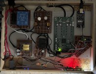
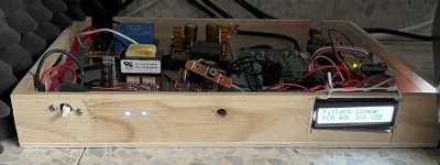
Last status of DAC DAM1021 project for today.
Finished HW side - beta-release (maquette) in box for review layout.
HW has 2 power transformers. First used to power DAM 1021.
Power supply has 2 stabilization rails based on LM317 with head-sync with output ±9V.
Second divided to power Arduino NANO by 12V output plus second output used for relay control.
Arduino required more time to power on and miss start up serial output from DAM 1021, relay on 24V control power used to delay power on time for DAM 1021. Arduino start first till the LCD and Serial interface has come to be stable and thaen using digital output pin set 5V out on transistor based key. Key on enables relay 24V control power and 9V come to power on DAM 1021.
One button used to switch filters in loop on DAM and 2 leds (power and functional) show what currently happen inside.
LCD provide full information about input used, filter set and current stream( PCM and bitrate).
FW on Arduino has several issues like o exit from uManager currently.
Next steps will be to fix Arduino SW and prepare original box planed.
Attachments
Hi forum.
Currently I'm stuck with some issue with DAM output and hope will have help with this here.
Arduino Nano using HW Serial interface connected to serial output from DAM DAC.
In FW I'm sending commands to enter uManager, set specific filter and exit from monitor using button press.
+++ command sent to enter monitor succeed.
But during loop() in Arduino code I'm doing next:
while (Serial.avaliable() )
{
Parse( Serial.read());
}
I'm doing this ever I entering to loop()
But I see output from DAC is not completely read. I don't see end of line (all bytes over 64 bytes are absent).
I can't understand why, because the speed of Serial is should be less from the speed of get data from.
I have no problem with this logically because in this case I'm not miss any required data. When I'm changing the filter I have just small output like
Input: set filter soft\r\n
Output F5\r\n#
In that case I will read the filter set and will parse correctly.
But I have issue with all next commands sent to serial DAC input.
All of them are returning Invalid Command output.
I have no idea why just first command are succeed always. Because no issues between commands found. The same command for test are sent to DAC and only first has been succeed.
Any ides for this?
Board rev7 and DAC FW 1.24
Thanks.
Done with no changes.Clear/flush your command buffer before every command?
flush() called always before printl function.
Clean - what is really means?
Clear output in serial should be done automatically by reading data but I see no clean action - cyclic buffer somehow lost end of buffers.
Input buffer clear is not present in Serial lib.
I tried also Serial.end() with reinit by Serial.begin and wait while !Serial in loop but have no effect.
More than - I have tested Serial.end with Serial.begin after sending "+++" command and have received full output after reinit of Serial still present in internal buffer of Arduino. It look like a big issue inside.
- Home
- Vendor's Bazaar
- Reference DAC Module - Discrete R-2R Sign Magnitude 24 bit 384 KHz