Note to readers - my scart in #9695 do not show the MCLK output. It shows when and how much the oscillator was ordered to change. So the lines between the dots mean absolutely noting. Between the dots, the i2c is silent - no orders given.
//
//
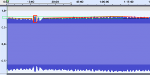
View attachment 915526
The x in the trace is the time of the sample was taken. They are slightly more than 0.2s appart.
On 23 September last year Soren stated that "The clock get updated at most once per second."
What's going on here?
If the FIFO were transparent and updates were at most once per second and the settling time after a small clock change was as fast as stated there would be no room for the clearly audible differences.
I think we in the end agreed in #9799 that it is approx. 2/sec.
So I envision a "calm" to be found if this is corrected and would perhaps unfold if we can listen to a "left alone" Si714. But this will need a quite good system, good filters, and an experience of listening to live music to appreciate. But hey, if you aim for SOTA... this is what it takes.
//
So I envision a "calm" to be found if this is corrected and would perhaps unfold if we can listen to a "left alone" Si714. But this will need a quite good system, good filters, and an experience of listening to live music to appreciate. But hey, if you aim for SOTA... this is what it takes.
//
Last edited:
I think we in the end agreed in #9799 that it is approx. 2/sec.
So I envision a "calm" to be found if this is corrected and would perhaps unfold if we can listen to a "left alone" Si714. But this will need a quite good system, good filters, and an experience of listening to live music to appreciate. But hey, if you aim for SOTA... this is what it takes.
//
Yes, the measurements appear to be at odds with Soeren's statement.
I find the differences pretty obvious on my systems, something is going on there...
1 or 2 per sec - I'm not sure its that of a big difference... Well just so that we are clear about the situation - no one has heard a 1021 with a stable (not-continuously-adjusted) Si514. I suppose you mention difference when using different digital sources. I was not. Not in this case anyway. All this because it doesnt seem to make a big difference if you feed it a stable clock or not - it's rather up to random luck how you happened to start playing wrt. the two involved clocks frequency and how it will behave the next 10 minutes... sad really.
//
//
Last edited:
1 or 2 per sec - I'm not sure its that of a big difference... Well just so that we are clear about the situation - no one has heard a 1021 with a stable (not-continuously-adjusted) Si514. I suppose you mention difference when using different digital sources. I was not. Not in this case anyway. All this because it doesnt seem to make a big difference if you feed it a stable clock or not - it's rather up to random luck how you happened to start playing wrt. the two involved clocks frequency and how it will behave the next 10 minutes... sad really.
//
I have tried it so often and in so many different ways that I'm quite sure it is not random luck when it comes to the RME internal vs. external clock. The effect is predictable and reproduceable. I just don't know what it is.
I did more tests regarding the quarter-sample-frequency (11025 Hz @ 44100 Hz) amplitude variations my DAM1021 produces. I have only observed these variations at that very frequency (11025 Hz) auditioning at 44,1 khz. The amplitude goes as much as 2.8 dB below the corect amplitude (same amplitude as rest of the spectrum not affected by the oversampling filters). Frequency of the amplitude modulations in my tests varied between around 0.5 Hz to 0.05 Hz.
It occured irrespective of the clock source. The interesting thing is: It goes away after some time (10 minutes or so) after the clock source is selected and then stays at the correct amplitude. Change the clock source (at the sound card feeding the DAM) and it returns. I can upload recordings if anyone is interested.
Any idea what is going on?
Last edited:
Yes - this is the playback frequency where the inter-over phenomena is at it's worst. My take is that you actually hear the inter-over effect i.e. when it is at a lower level it is when the Fs is not 44,1 but a bit higher or lower. The level phenomena that you experience is a PCM system characteristics when the sampled frequency interfere with the playback frequency. See more here. But I'm not sure it should be an error that the PCM theorem predicts..? Anyways, as it its absolute worst at Fs/4, I would believe that when playback of a perfect pitch Fs/4 tone in combination with a varying playback Fs, as in the DAM, the result would be that the Fs/4 tone will vary in level and in this case - with 0,5 Hz to 0,05 seems in the right ballpark. Some 2 Hz should also be detectable as we indeed see clock changes up to 2 times per second.
Please post the recording.
//
Please post the recording.
//
Yes - this is the playback frequency where the inter-over phenomena is at it's worst. My take is that you actually hear the inter-over effect i.e. when it is at a lower level it is when the Fs is not 44,1 but a bit higher or lower. The level phenomena that you experience is a PCM system characteristics when the sampled frequency interfere with the playback frequency. See more here. But I'm not sure it should be an error that the PCM theorem predicts..? Anyways, as it its absolute worst at Fs/4, I would believe that when playback of a perfect pitch Fs/4 tone in combination with a varying playback Fs, as in the DAM, the result would be that the Fs/4 tone will vary in level and in this case - with 0,5 Hz to 0,05 seems in the right ballpark. Some 2 Hz should also be detectable as we indeed see clock changes up to 2 times per second.
Please post the recording.
//
I don't see how this would have anything to do with inter-sample peaks (a phenomenon I am aware of from the mastering perspective). The link describes it as a predictable occurence resulting from digital filtering, which makes perfect sense intuitively (filters ring and create overs).
But here we are looking at something that happens during playback (preceding the digital filters), dynamically, seemingly in conjunction with some clocking artifact (so again, after the filter) and as a lowering rather than an increase of amplitude. I also used different FIR1 and FIR2 filters last year when I noticed the exact same effect.
I will listen to the recording I made yesterday again, but I think the sound quality was better after waiting out for the effect to go away.
Will post files later today.
I didn't worry. Plugged in and the connection was there ... with this USB to RS232 adapter
DIGITUS USB auf Seriell Adapter - RS232 Konverter - USB: Amazon.de: Computer & Zubehor
Got it today - works! Great solution, thanks again! I can finally store the old laptop away again. 🙂
Here are the files:
Dropbox - 11025.zip - Simplify your life
DO NOT LISTEN TO THOSE FILES!
They are not meant for playback and can destroy speakers and ears if played loud!
Look at them in you audio software.
I put everything in one file:
0:00 to 7:20 is various ways of clocking without letting the clock "settle".
From 3:16-3:25 I changed the frequency to a little higher than 11025 and from 3:25-3:50 to a little lower.
After 7:20 there are recordings from two different occasions where I let things "settle" for around 10 minutes or more.
Between 8:40 and 9:20 it can be seen that the amplitude did "break" a little again, going down a maximum of about 0.1 dB
The second file has a notch filter applied at 11025 to analyze the residual. There wasn't much I was able to gleam from it.
But, I think there is something going on with the phase here: The peak meter shows a change, but the RMS meter stays rock solid at all times.
Then I looked at it with a scope. The signal with the amplitude intact shows a triangle pattern. But the signal with the varying amplitude shows a pattern continuously varying between triangle and "triangle with top shaved" (clipped). This does indeed show a resemblances to tnt's inter-sample-peak link. I just don't see how this would work in the analog domain, since the peak output is actually lower. I had the internal volume set relatively high to compensate for the output lowered by the filter (no real world problems like distortion detected), but this might be it. I still don't see how distortion would happen in the digital domain in relationship to the clock, which only comes into play after the filters at the point of conversion...
Last edited:
The reason is that when the clock in the DAM varies, it's like tuning the focus on a camera on F=0.95 at 15cm. What happens is that when in "focus" i.e. = Fs/4 the inter-over situations is at it's peak. Razor thin depth of field 😉
//
//
The reason is that when the clock in the DAM varies, it's like tuning the focus on a camera on F=0.95 at 15cm. What happens is that when in "focus" i.e. = Fs/4 the inter-over situations is at it's peak. Razor thin depth of field 😉
//
That does not explain it for me, I'm afraid. 🙂
I did correct my above post, it is a triangle wave, not a sawtooth wave.
Why did you choose Fs/4 as a test signal? It can be cumbersome due to its relation to Fs. When DAM varies its clock, and replaying Fs/4, it will be really critical as it drifts in and out of the perfect Fs/4 situation - I can imagine that this can be seen very dramatically on a scope...
//
//
Why did you choose Fs/4 as a test signal? It can be cumbersome due to its relation to Fs. When DAM varies its clock, and replaying Fs/4, it will be really critical as it drifts in and out of the perfect Fs/4 situation - I can imagine that this can be seen very dramatically on a scope...
//
Originally I chose it to see jitter sidebands. But then I noticed the amplitude changes.
Aha. How do you measure jitter side-bands?
//
Doesn't work that well this way. ;-)
I measured the DAM-clock and simultaniously made a recording of the FS/4-sine that was played by the DAM. The DAM was fed by SPDIF and the SPDIF clocking was made by the ADC clock, so the effects you see are essentially due to the DAM.
You cleary see the same picture in the osscilation of the clock as in the envelope of the recording. Especially the events with big oscillation are at the same location in both plots.


You cleary see the same picture in the osscilation of the clock as in the envelope of the recording. Especially the events with big oscillation are at the same location in both plots.
- Home
- Vendor's Bazaar
- Reference DAC Module - Discrete R-2R Sign Magnitude 24 bit 384 KHz