Sitting on the drop out edge is not an ideal situation. Many regs needs, even if they do work, a few volts to do their best.
//
Super clean on the scope, never felt the need to revisit it. I guess it helps when the supply side is also clean.
Stacked on C40, there are also a few more ceramics & a 10uF tantalum on the output of the reg. Going from 5 to 3.3v with the current load it does meet the dropout voltage requirement by a hair ~0.3v.
If I had the chassis room I would have supplied 3.3v+1.8v by LT3402+4th transformer but I also wanted this build to be compact, not get too hot and thus have low power consumption. It draws around 10 watts for everything including the front panel display + headphone amp.
I tried a 47uf tantalum in place of the 1500uf polymer and it was clear that the latter was subjectively superior.
Have you measured or calculated the impact of your decoupling arrangement wrt to impedance/resonances? I know mixing tantalums and ceramics can be especially problematic in this regard, but I do not know enough to measure it. Ceramics of the same size in parallel as decoupling caps is generally not considered a problem.
Last edited:
There is indeed more than one issue:
a) Drift
b) Changes in performance when changing the clock source
Drift is only a problem for recording and multichannel applications.
Source clock dependence is a problem for everyone. I am not so sure that changes in performance when changing the clock source are due to frequent re-setting of the DAM1021's clock. Why? Because I don't think my incoming clocks are so bad. And because the changes are so predictable/reproducible.
I wouldn't rule out the possibility that the quality of the original clock gets past the FIFO in some other way. But we don't know. And without options to configure the reclocking ourselves we won't find out.
There is indeed more than one issue:
a) Drift
b) Changes in performance when changing the clock source
Drift is only a problem for recording and multichannel applications.
Source clock dependence is a problem for everyone. I am not so sure that changes in performance when changing the clock source are due to frequent re-setting of the DAM1021's clock. Why? Because I don't think my incoming clocks are so bad. And because the changes are so predictable/reproducible.
I wouldn't rule out the possibility that the quality of the original clock gets past the FIFO in some other way. But we don't know. And without options to configure the reclocking ourselves we won't find out.
You could compare the phase noise (or the jitter in time domain) measured at the input (the incoming signals from the source) with the phase noise measured at the output of the reclocker (close to the DAC switches).
That's what we have done with the famous FIFO buffer.
As I said several times the Allan Deviation is useless in audio application.
I could, if I had the equipment. ;-)
I could, if I had the equipment. ;-)
I own the gear so I will make the measurements, although I cannot measure your source.
I will measure the incoming signals from a Raspberry Pi standalone source comparing with the signal feeding the DAC switches.
The gear is expensive, but maybe someone could afford it by the profits from sales, since we have bought the instrument and we are simply hobbyists without any commercial interest.
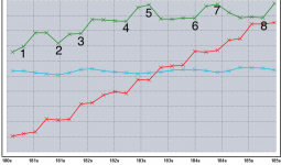
Here some measurements on how the offset of the I2S clock to the DAM clock (before locking) influences the clock adjustment of the DAM.
I measured the DAM clock with no signal locked to the DAM first, then adjusted the I2S clock to that frequency plus an offset, then played an signal. I did that for offsets of approximately 0Hz, 1Hz, 5Hz, 10Hz, 20Hz, 50Hz and 100Hz.
View attachment 914797
Well we see that the magnitude of the oscillation at start as well as in the stable phase later differ, but the offset seems not to be the determining quantity.
For offsets of 20Hz and bigger there is an instant adjustment at the start.
Thanks! Is it a correct interpretation of your measurements that the average frequency deviation is the greater long term, the greater the initial offset (with the red 10 Hz deviation being the exception)?
Thanks! Is it a correct interpretation of your measurements that the average frequency deviation is the greater long term, the greater the initial offset (with the red 10 Hz deviation being the exception)?
No. The very short line in the beginning, with y=0, is the frequency of the DAM-clock before applying the signal with the offset clock. The plots are thus showing the difference to the initial frequency.
The "big-picture" jump up and staying up there is the tracking of the offset. The jump up is thus bigger the bigger the offset is but this the desired behavior.
The interesting thing is how the jump up and stabilizing to the offset frequency happens in detail. E.g the plot for 50Hz offset (brown) oscillates less, as well in the beginning, as in the "stable" phase than e.g. the 100Hz or the 10Hz plot.
Mmm, the Q value of the circuit seem to differ depending on the circumstances... odd for being software only... But I'm sure Sören will improve this soon. Or I hope he will at least.
Sören - any plans? Please share.
//
Sören - any plans? Please share.
//
My current hypothesis is that the effect could be due to limits in resolution of the frequency measurement of the DAM. So if the DAM-measurement matches the reality well then we see less oscillation. This could be tested by offset measurements in finer steps ... but I assume Soren can verify this. I want to re-assemble my DAM for listening music with it again 🙂
I didn't worry. Plugged in and the connection was there ... with this USB to RS232 adapter
DIGITUS USB auf Seriell Adapter - RS232 Konverter - USB: Amazon.de: Computer & Zubehor
That did the trick. Updated and ready to play around. Thanks a lot!
One more thing why I am convinced that it is the quality of the incoming clock and not its frequency vs. the target frequency (or rather the internal frequency of the DAM1021 deemed correct for that sample rate): I can change the sampling frequency in incriments of 0.01% in my sounds card. This makes no audible difference once the DAM1021 has adjusted.
Well... just one change will probably be hard to catch if not impossible. But if its ongoing constantly.... well... it makes the clock "unstable" on a music listening scale... I don't like it. I'm not worried so much about the size of the clock change as the intensity of poking the clock.
zfe - can you extract some change intensity figures from your last tests? I.e. average clock adjustments per second, most intense second, longest time between changes etc?
I have the attached data but I'm a little bit uncertain of the correctness.... it source comes from a Si i2c trace.
//
zfe - can you extract some change intensity figures from your last tests? I.e. average clock adjustments per second, most intense second, longest time between changes etc?
I have the attached data but I'm a little bit uncertain of the correctness.... it source comes from a Si i2c trace.
//
Attachments

Last edited:
Well... just one change will probably be hard to catch if not impossible. But if its ongoing constantly.... well... it makes the clock "unstable" on a music listening scale... I don't like it. I'm not worried so much about the size of the clock change as the intensity of poking the clock.
zfe - can you extract some change intensity figures from your last tests? I.e. average clock adjustments per second, most intense second, longest time between changes etc?
I have the attached data but I'm a little bit uncertain of the correctness.... it source comes from a Si i2c trace.
//
Well there is a scale on the y-axis 😉
E.g. for the red trace the first maxima is about 10^-6 (of the nominal frequency of 22.x MHz) so about 22Hz. In the stable phase, the swing is about 1/3 of a grid, so around 0.2*10^-6 = ~5Hz.
The measured clock was the FPGA-master. The SI514 runs at double frequency.
Not the change of freq but how often it is changed.
//

The x in the trace is the time of the sample was taken. They are slightly more than 0.2s appart.
Would you think it is correct to assume that we see both clock drift and changes combined but at the places I drew numbers, are the actual occasions where a i2c order to change clock was made? That would jive with my findags of about 2 changes over i2c (traced!) per second when most intense.
//
//
Attachments
Last edited:
- Home
- Vendor's Bazaar
- Reference DAC Module - Discrete R-2R Sign Magnitude 24 bit 384 KHz