Thanks a lot.
I have some doubts in the absolute numbers on the y-scale. For the 1021-v1 I measured, roughly:
the Si514 49Mhz (48kHz*64*16), the FPGA master clock pin half of that, and the clock of the shift-register-out 1/16 of the Si514.
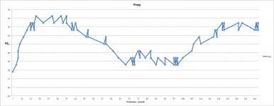
But the "1Hz" steeped oscillation as pictured should be what is happening.
I have some doubts in the absolute numbers on the y-scale. For the 1021-v1 I measured, roughly:
the Si514 49Mhz (48kHz*64*16), the FPGA master clock pin half of that, and the clock of the shift-register-out 1/16 of the Si514.
But the "1Hz" steeped oscillation as pictured should be what is happening.
What do you mean by ""1Hz" steeped oscillation"?
The hex sent to the SI seem to make up for 36...Mhz?
Here is one sequency of writes to the bus starting for reg 5 and ing with reg 9 each followe by its written value:
272934, 5 (reg)
272970, B8 (data)
273090, 6 reg...
273126, 4E
273245, 7
273282, EB
273403, 8
273438, 78
273559, 9
273594, 8
=> 878EB4EB8
Si514 manual:
Register 5 = 0x57 (M_Frac[7:0])
Register 6 = 0x45 (M_Frac[15:8])
Register 7 = 0xA4 (M_Frac[23:16])
Register 8 = 0x42 (M_Int[2:0],M_Frac[28:24])
Register 9 = 0x05 (M_Int[8:3])
Probably I overlooked something in the coding? Reg 8 and 9 seems coded different from 5-7?
//
Last edited:
Yepp - I see the problem now 🙂
Whats before the comma (49,xxx Mhz) sign is in the M_Int part right?
//
PS. So the plot is correct when it comes to tenths of khz region anyways...
Whats before the comma (49,xxx Mhz) sign is in the M_Int part right?
//
PS. So the plot is correct when it comes to tenths of khz region anyways...
Last edited:
From post #828:
"7) Reclocking FIFO with automatic clock tracking works like a charm, syncronize to < 1ppm at anything withing 1% range, and then tracks using a software PLL with 0.02 Hz Lowpass Filter and with 0.02ppm step changes."
Are we still on this spec or has div "sync/plop/etc problems" forced this to be changed?
0,02 Hz corresponds to 50 seconds...
I interpreted this as clock changes should be needed less seldom than once every 50 seconds?
//
0.02ppm of 49Mhz is about 1Hz - fine that's another confirmation.From post #828:
"7) Reclocking FIFO with automatic clock tracking works like a charm, syncronize to < 1ppm at anything withing 1% range, and then tracks using a software PLL with 0.02 Hz Lowpass Filter and with 0.02ppm step changes."
...
//
O.K. to get an idea on the effect for the audio side one could look at an audio-band square wave played by the DAM (unfiltered).
It's frequency would also change also by 0.02 ppm (so 20uHz for a 1kHz square wave).
You get thus exactly the same curve only with appropriate scaled y-axis (divided by 49000).
No idea if that is audible, but as it easily could be avoided by introducing some damping why not get rid of it.
So, the reason i like this dac is cause it's got more wow&flutter than a cheap turntable? 😛
Or is the plot a bit exaggerated?
Or is the plot a bit exaggerated?
So, the reason i like this dac is cause it's got more wow&flutter than a cheap turntable? 😛
Or is the plot a bit exaggerated?
It's effect on a audible tone is related like the frequency the clock oscillates on and the change in frequency - in ppm or 100 times better territory.
I had a 1000x fault in my absolute values - but relation is the same in the corrected one.
Got absolute pitch? 🙂
//
Last edited:
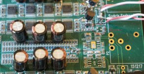
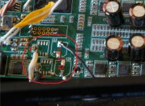
Can you post a few pictures? One with bypassing regs, one with muting fets ....
I'm about to do the VREF and transistor mod and add Salas reg to power the board. I could remove the muting fets too. I have rev2 board.
Regards
Hi Flikoman, I apologize for the delay in responding. Here are some pics of the reg bypass and muting fet removal. I used chip quik remove the regs. Makes it easy.
Attachments
For a 10kHz signal, to make the 0.02ppm steps visible in the FFT one would need to sample the audio output data for at least 3 hours ... perhaps I should try to do that some day 🙂
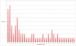
Yes, I was also wrong about the change intensity in my first assesemnt of the data - sorry about that. Chart below shows the distribution of duration between frequency changes for the 2 minute recording. Almost all these changes was 806 hz. A few was 805 wich I found strange...
Now, if one had access to the variation of the input timing....🙂
//
PS. Don't really fancy all that poking of the clock - give the clock a chance to do it's best I'd say 😉 ... if one aims for a "Reference DAC Module...".
Now, if one had access to the variation of the input timing....🙂
//
PS. Don't really fancy all that poking
of the clock - give the clock a chance to do it's best I'd say 😉 ... if one aims for a "Reference DAC Module...".Attachments
Last edited:
Hm, well, yes ...
So these 806 Hz is what?
The change rate of the frequency of the clock ... then where it that in the attached plot?
The step of change of the clock frequency ... I thought we agreed that was around 1Hz?
So these 806 Hz is what?
The change rate of the frequency of the clock ... then where it that in the attached plot?
The step of change of the clock frequency ... I thought we agreed that was around 1Hz?
The plot shows the rate of 806 Hz changes.
806 Hz is the step that Sören used to change the clock. Always in steps of 806 Hz.
//
806 Hz is the step that Sören used to change the clock. Always in steps of 806 Hz.
//
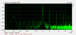
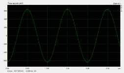
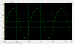
Distortion on the right channel
I have a V1 DAM with vrefmod and have been very satisfied for a few years now. However, recently I noticed some distortion on the other channel while listening. Did some quick and dirty measurements once I got a reasonable USB-audio interface and noticed that the right channel indeed has some weird happening there.
The overall amplitude of the signal is smaller and it seems that the positive side of the voltage swing has some sort of error on it. Looking at these, any ideas about the possible cause and advice whether I should start troubleshooting further or should I just get a new board?
Attachments

I have a V1 DAM with vrefmod and have been very satisfied for a few years now. However, recently I noticed some distortion on the other channel while listening. Did some quick and dirty measurements once I got a reasonable USB-audio interface and noticed that the right channel indeed has some weird happening there.
The overall amplitude of the signal is smaller and it seems that the positive side of the voltage swing has some sort of error on it. Looking at these, any ideas about the possible cause and advice whether I should start troubleshooting further or should I just get a new board?
Clearly a problem with the vrefs, check them....
Clearly a problem with the vrefs, check them....
Thanks for the reply. I measured the vrefs. The negative side seems to be off. While the others measured approx 3.99 V, the negative side was at about -2.32 V.
What should I look next?
- Home
- Vendor's Bazaar
- Reference DAC Module - Discrete R-2R Sign Magnitude 24 bit 384 KHz