check vref voltage levels
could be anything from a dead or dying 4v reg to a blob of solder causing a short somewhere
good chance its fixable
pics might help
Thanks, since the problem is left, I only need to check this part, right?
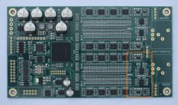
Attachments
well subjective results wont mean anything to some
tested
jlsounds oem
2 versions the new and old diyinhk xmos units
amanero
el cheapoish sd card player i2s
and all with and without synchronous reclocking pre i2s isolators when i had em in
all the xmos ones sound similar but not the same other ones are more dissimilar
i don't know why there is differences it makes little sense
but i do have preferences
it would be an easier life if you believe there isnt any differences and my ears just aint workin good
im sure the fpga system levels the playing field somewhat though
do agree the fact but technically there shouldnt be any difference as the fpga reclocks the incoming signal so why there is sonic difference observed.
Can soren explain this?
checked vref, got only 0.19v from one end (the very bottom on my pic above), does it mean 4 v reg dead?
The first thing to check would be to see if the I2S data coming from these sources is really identical. I mean not just the software setup which "should" produce bit perfect playback, but the actual electrical signal on the wire.
There may also be differences in noise , slew rate and ringing of the I2S signal and in noise of the isolator power. If some differences can be seen on the other side of the isolators, and there is a correlation between what is measured on each side of the isolators, it would explain some of these observations.
Verifying the actual recklocking using a black box approach could be a little tricky. One interesting test might be to use a function generator for the I2S mclk source and to frequency modulate it with various signals, not changing anything else in the setup. If the reclocking works as advertised, sound should be indistinguishable in all cases.
and
do agree the fact but technically there shouldnt be any difference as the fpga reclocks the incoming signal so why there is sonic difference observed.
Can soren explain this?
Actually, technically there should be a difference!
I've based my working understanding of why isolators and reclocking don't totally eliminate differences in upstream devices on this post by John Swenson:
Uptone Audio Regen - Page 7
My read of what John says is that clean I2S signals and good power AT THE CHIPS still remain important for the best results. And there are other factors, but these are the main ones my puny brain can encompass.
Knowing that someone like John, who does very high-end IT HW power system designs during the day and in his spare time designs very successful and cutting edge high-end audio devices like the Sonore Rendu Signature and up-coming uRendu, the Uptone Audio Regen, and the Bottlehead DAC) clearly states that isolation and reclocking does not eliminate upstream source impacts on downstream sound quality and can so clearly describe the mechanisms by which this happens has me not questioning what I'm hearing nor looking for a cause. BUT this is the first time I've had an isolated and asynchronously reclocked setup in my system with two very different sources and actually heard the two sources not sounding the same.
Also implied in what John wrote are a number of potential mitigations to the issue. Good power AT the isolator chips should help, as should good power to the source. Various isolator chips could produce different results... John in some other posts says he prefers the GMR-type isolators, while the ones selected for the DAM are the RF ones. I believe there are compatible ILxxx devices that could be swapped in to see what difference that might make.
I think most people who have purchased and used an Uptone Audio Regen on their USB audio signal feed can attest that John is on to something here.
Greg in Mississippi
P.S. I've seen similar, but less detailed comments on the limits of isolation and reclocking by Ted Smith, the designer of the PS Audio Directstream family of DACs, but have not been able to find them.
It seems these problems should be eliminated by using a transformer balanced AES/EBU input, shouldn't they?
checked vref, got only 0.19v from one end (the very bottom on my pic above), does it mean 4 v reg dead?
check continuity between that 4v reg and gnd for a short
its prob dead by now
the question is why did it fail?
do agree the fact but technically there shouldnt be any difference as the fpga reclocks the incoming signal so why there is sonic difference observed.
Can soren explain this?
Not really, the FPGA reclocking/fifo really should make all the incoming audio data look the same, but there could be a couple of things being affected:
The incoming I2S clock or data are so dirty that there are bit errors, especially when isolated as the isolators add a little jitter.
Different noise sneaking though the system, especially when not isolated.
And my usual: Psychoacoustics....
My plan:
- use Amanero board for I2S
- use only one DAM board (v3)
- use Raw or buffered RCA for output
- use SALAS BiB +-12V
- use Salas Ref-D (+3.3V) for Amanero board to isolate it from USB +5V
- make simply mods that can contribute to the better sound
Where I’d like to get confirmation or opinions are the following:
When I use external 3.3V for Amanero I only have to cut 1 trace as described at post #878. How to connect external 3.3V to Amanero board? To C27 as the post #878’ picture says or I can use GND and 3.3V output of the Amanero’s output connectors, does it matter?
Does it worth to make shift register VRef mod when I use v3 board and Salas PSU? (https://hifiduino.wordpress.com/2015/07/12/soekris-dac-modding-vref/)
If yes. The explanation says that the bigger the capacitance the better. The description recommends Nichicon FPCAP RR7 16V 330uF while in this product range with 6,3 or 10V there are bigger ones. Does it worth, is it possible to use for example 6.3V 1000uF, maybe a pair of them in parallel. (In this case the capacitance doubled while the ESR as I think is halfed)?
For the output capacitor of the buffer. Soren officially suggests 47uF X5R in and two 0.1R resistor parallel with the output series resistor and feedback capacitor in post #3108. At https://hifiduino.wordpress.com/2015/07/12/soekris-dac-modding-vref/ the author suggests to make short the feedback capacitor instead of 0.1R.
Thanks
Not really, the FPGA reclocking/fifo really should make all the incoming audio data look the same, but there could be a couple of things being affected:
The incoming I2S clock or data are so dirty that there are bit errors, especially when isolated as the isolators add a little jitter.
Different noise sneaking though the system, especially when not isolated.
And my usual: Psychoacoustics....
Not that I have any clues that it is the case, but thinkable is also:
- An error in the program or algorithem of the reclocking/fifo
- The clock tracks the input frequency if needed. Thus (very) low frequency jitter gets trought the reclocking/fifo. The reclocking/fifo infact can be seen as a jitter low pass filter. ... maybe we are still able to hear very low frequency jitter ... no idea.
as far as differences between sources of seemingly "correct" digital data ...
Just as with music where what happens between the notes makes a difference;
I speculate there is something happening between the 1s and 0s.
We have to polish these digits so they are distinct and give them a background of silence for them to be easily distinguished so there is little need for error correction.
Of course, within the digital environment SILENCE will never be achieved but the closer we get to silence the better off we are.
Yes, I am ready for the skeptics to make fun of my assertion!
Hey Rick, I hope I have understood you correctly. Yes, the peace between the signals is important and not just the DAC. The problem swinging we want to also remember specifically ask to speakers or headphones, who measures as much, the place sometimes strange little rest there where it needs to be. But, if I decide for the input logic to understand ones and zeros in the correct time then I rage them properly. The data rate when listening to music rarely exceeding 10Mbit / s, which is not really much, since my computer can do more, much more, and it does not lose one bit. The whole shebang is offered as a digital tuning in consumer electronics for over 30 years is virtually all nonsense, more absurd than arm-thick cables and singing bowls. But people want to be different from others and exceed the most, because helping an exaggerated individualisation, no matter what it costs, and really does. After 40 years of Electrical Engineering I'm a bit more down to earth and do not equal all want to hear my ears in all the excitement. Only in the blind test, you can trust your ears only.
I have bypassed the isolators and hear an improvement.
I would not have paid $500.00 for the improvement but since it was free ...
The thing about these measurements is, so far, we can only measure what we can measure and that does not seem to be enough.
One wishes that the "measurers" would spend their time trying to find a way to measure what the listeners are hearing instead of saying what they hear does not exist. Well, it certainly does not exist for them since they never bother trying the things the listeners have found are useful. The listener camp would welcome a measurement that could identify the good sounding component from the bad. But like a cure for cancer this seems to be elusive.
I am speaking of the subtle qualities that separate the average from the really good.
One has to be reminded that all science begins with an observation not a text book. If something is not tried then no one will ever know.
No one tries more things than nige2000 and that would make him - suspiciously similar to a scientist.
Hi Rick,
Good observations. I would like to try bypassing the dam isolators as I have an isolated USB to i2s converter. Could you please send a picture to see how you have done this.
AS nige2000 has warned you must have a very clean (quiet) digital input. I am using the SDTrans which fills the bill.
I am a minimalist so I simply have run the cable (the coax as supplied by HIROSE for the uFl cables) from the SDTrans to the output pads of the isolators. Per Nigel's drawing, it is back in the thread somewhere.
The output pads are of a good size so soldering to them is simple.
I said before if this mod cost five hundred dollars it would not be a good use of money but for nothing, and if your previous component will not make a mess of things, it is worth the trouble.
There is far more to be had with Nigel's powering scheme but the isolator mod is good practice for going further.
Much to SOEKRIS's dismay my board is almost clean of the components placed upon it.
I want to make it clear that I have nothing but respect and appreciation for the work of electrical engineers, especially those who turn their gaze to audio. When I have a problem it is when so many decide that the "work" is done and we can sit back and be pleased with ourselves. It seems to me that when something is noticed it is a shame that someone would want to look into it further rather than the automatic dismissal we usually hear.
I have as much confidence in BLIND testing of audio gear as I would in thinking I could judge/appreciate a painting better with my ears blocked. It is ridiculous in so many ways.
Consider the apparatus used to perform the "test". Anyone with much experience with highly resolving audio gear knows that every switch, every length of wire affects the sound. The apparatus will likely mask the resolution of the device being appraised. It is no surprise that most of the time these tests are inconclusive.
Then there is the short interval of listening time. Grotesque differences would be easily heard in this fashion but subtleties take some time to be perceived and that is what we are listening for most often.
I think the idea was developed as a "gotcha" - a sure way to prove "there is no difference". The motivations for this are numerous.
Long term listening is the only way to know for sure. None of this stuff is close to perfect. Eventually the ear/brain will find the component in question annoying. All of them are eventually which is why we like to change the sound of our systems. Some make subtle changes to a basic system architecture and some change everything to combat this listening fatigue.
The former approach, obviously, is the path to finding out what works since there is a baseline.
There should not be a conflict between listeners and engineers, but I find the latter to be responsible for it more than the listeners. The listeners are observers. It is natural for all of us to think we have "solved the problem" but that is very depressing since the problems of audio reproduction are anything but solved and it would be sad to think there are no improvements possible. There certainly will not be if it is decided there is little left to do.
Not really, the FPGA reclocking/fifo really should make all the incoming audio data look the same, but there could be a couple of things being affected:
The incoming I2S clock or data are so dirty that there are bit errors, especially when isolated as the isolators add a little jitter.
Different noise sneaking though the system, especially when not isolated.
And my usual: Psychoacoustics....
True I had a feeling that the input might be soo bad that it might be the reason why the sonic difference is observed.
So are the isolators are used in the oem module?
Hello, Søren,
I've ordered V3 board on the way. Thanks for the wonderful board. However, I am still wondering if you might offer some version without opamp and with Vref easy to supply with own solution. Thanks.
WYAN
I've ordered V3 board on the way. Thanks for the wonderful board. However, I am still wondering if you might offer some version without opamp and with Vref easy to supply with own solution. Thanks.
WYAN
True I had a feeling that the input might be soo bad that it might be the reason why the sonic difference is observed.
So are the isolators are used in the oem module?
I looked at the board on soekris.dk website and it does not look they are there.
AS nige2000 has warned you must have a very clean (quiet) digital input. I am using the SDTrans which fills the bill.
I am a minimalist so I simply have run the cable (the coax as supplied by HIROSE for the uFl cables) from the SDTrans to the output pads of the isolators. Per Nigel's drawing, it is back in the thread somewhere.
The output pads are of a good size so soldering to them is simple.
I said before if this mod cost five hundred dollars it would not be a good use of money but for nothing, and if your previous component will not make a mess of things, it is worth the trouble.
There is far more to be had with Nigel's powering scheme but the isolator mod is good practice for going further.
Much to SOEKRIS's dismay my board is almost clean of the components placed upon it.
I want to make it clear that I have nothing but respect and appreciation for the work of electrical engineers, especially those who turn their gaze to audio. When I have a problem it is when so many decide that the "work" is done and we can sit back and be pleased with ourselves. It seems to me that when something is noticed it is a shame that someone would want to look into it further rather than the automatic dismissal we usually hear.
I have as much confidence in BLIND testing of audio gear as I would in thinking I could judge/appreciate a painting better with my ears blocked. It is ridiculous in so many ways.
Consider the apparatus used to perform the "test". Anyone with much experience with highly resolving audio gear knows that every switch, every length of wire affects the sound. The apparatus will likely mask the resolution of the device being appraised. It is no surprise that most of the time these tests are inconclusive.
Then there is the short interval of listening time. Grotesque differences would be easily heard in this fashion but subtleties take some time to be perceived and that is what we are listening for most often.
I think the idea was developed as a "gotcha" - a sure way to prove "there is no difference". The motivations for this are numerous.
Long term listening is the only way to know for sure. None of this stuff is close to perfect. Eventually the ear/brain will find the component in question annoying. All of them are eventually which is why we like to change the sound of our systems. Some make subtle changes to a basic system architecture and some change everything to combat this listening fatigue.
The former approach, obviously, is the path to finding out what works since there is a baseline.
There should not be a conflict between listeners and engineers, but I find the latter to be responsible for it more than the listeners. The listeners are observers. It is natural for all of us to think we have "solved the problem" but that is very depressing since the problems of audio reproduction are anything but solved and it would be sad to think there are no improvements possible. There certainly will not be if it is decided there is little left to do.
Hi Rick, thank you I will dig further into this.
another thing to consider...
Soren suggests that none of this input stuff will matter, or perhaps "should" matter, because the signal is re-clocked in the FPGA before input to the ladder.
Now my understanding, expressed to me by digital engineers who I respect, is that re-clocking in an FPGA is not low jitter, and that such an output will actually have significant jitter, regardless of how accurate the masterclock source may be.
The best way to do this, as has been explained to me, is to re-clock after the FPGA, directly from the masterclock via a flip-flop, right before whatever is doing the D/A conversion. I suspect this approach is probably best:
FPGA/processing-isolation-reclock (flip/flop)-D/A conversion,
thus also providing some isolation from FPGA processing noise.
Thoughts? Has any J-test analysis been done/published on the output of the DAM?
By no means am I attempting to disrespect the work which has been put in on this project, and I am very thankful to Soren for bringing this product to market, especially considering the high price one must pay for any other discrete ladder DAC technology.
Soren suggests that none of this input stuff will matter, or perhaps "should" matter, because the signal is re-clocked in the FPGA before input to the ladder.
Now my understanding, expressed to me by digital engineers who I respect, is that re-clocking in an FPGA is not low jitter, and that such an output will actually have significant jitter, regardless of how accurate the masterclock source may be.
Of course, that's why the incoming jitter doesn't matter, assuming no bit errors, as it's reclocked and buffered so the dam1021 clock circuit define the jitter. But the clock oscillator and FPGA have low jitter, not as low as what's possible, but low enough that the dam1021 sounds pretty damn good.... Has actually been discussed early on in this thread.
The best way to do this, as has been explained to me, is to re-clock after the FPGA, directly from the masterclock via a flip-flop, right before whatever is doing the D/A conversion. I suspect this approach is probably best:
FPGA/processing-isolation-reclock (flip/flop)-D/A conversion,
thus also providing some isolation from FPGA processing noise.
Thoughts? Has any J-test analysis been done/published on the output of the DAM?
By no means am I attempting to disrespect the work which has been put in on this project, and I am very thankful to Soren for bringing this product to market, especially considering the high price one must pay for any other discrete ladder DAC technology.
If you look very close on the dac1101 and dam1121 pictures you might notice some small flip flops between the fpga and the shift registers 🙂
- Home
- Vendor's Bazaar
- Reference DAC Module - Discrete R-2R Sign Magnitude 24 bit 384 KHz