Why are youguys sosurprised about differences ? I have still to build this dac, runningcurrently a biii mono with ian's reclocker and waveio. Boards are ordered for a soekris mono-dac...
I can tell youthat its a huge diiference between my alix 1/mpdpup/sotm input system, so linux with mpd, or volumio and mod with rasperry (worse).
In theory it should not matter as xmos and reclocker should equalize, but in practise huge difference.
For the biii i am now gong to try a bbb with hermes andcronus, so avoiding xmos / usbcompletely.
I hopei can get something similar going with soekris'dac...or will build ian's reclocker into the chain...which is normally anyhow a very good idea.
https://hifiduino.wordpress.com/2015/01/30/building-soekris-r-2r-dac/
https://hifiduino.wordpress.com/2015/03/16/soekris-dam-1021-r-2r-dac-users-guide/
https://hifiduino.wordpress.com/2015/06/14/dam-1021-r2r-more-mods/
https://hifiduino.wordpress.com/2015/07/12/soekris-dac-modding-vref/
Read these. If you still have questions then, come back and ask 🙂
https://hifiduino.wordpress.com/2015/03/16/soekris-dam-1021-r-2r-dac-users-guide/
https://hifiduino.wordpress.com/2015/06/14/dam-1021-r2r-more-mods/
https://hifiduino.wordpress.com/2015/07/12/soekris-dac-modding-vref/
Read these. If you still have questions then, come back and ask 🙂
Wish I could get some help on these forums... But my questions are apparently too dumb.
Looking at you post a little ago, I assume that what you want to know....
The dam1101 datasheet says 7-15V DC, so that what it is, it doesn't matter what except that lower voltage would mean a little lower heat dissipated....
Would this be an okay transformer to use?:
VPM24-1040 Triad Magnetics | Transformers | DigiKey
In addition, in this image it suggests the use of a transformer with dual secondaries: http://i.imgur.com/tF108JI.jpg
Would a single 12v secondary be okay?
Lastly, if using the digital volume control, is there a need for a second transformer/additional power?
Single secondary will not work, since the DAC uses both positive and negative rail.
The transformer you have linked is two secondary windings of 12V, so 12-0-12, which if run directly into the DAC is to high voltage ( should be two secondaries of 7-8VAC), but if you are running a regulator between transformer and DAC board, as the picture shows, then you can be fine - if you have output voltage of 7-15VDC into the Dac board.
If running transformer straight into the dac - then this one would work (as an example) - http://eu.mouser.com/ProductDetail/...GAEpiMZZMvwUzoUXIIvydH8/j5UF54yTLz70HY%2by3c=
Last edited:
I have two Salas BIB lv boards (+/-) that I intend to use with said transformer. I purchased them as a partial kit but am not sure what additional parts I will need in order to achieve a VDC within the desired range of 7-15. If anyone could help in this regard and/or provide some sort of complete BOM for the Salas boards that would be much appreciated. Thank you.
Check the Salas BiB thread, there is a manual there which explains everything. If you still dont understand, take the question there - since it is a SSLV question rather than soekris dac 🙂
Last edited:
How would I use a dual positive power supply?
I'm told this will work, but not sure the best way to wire it.
bi-polar is simple and think I get that...but this is my attempt at Dual postiive...using some 4 position terminals and isulated barrier strips to essentially split the power from one PSU out to two DAM1021's. am I wrong in doing this?
I have a silverline O core transformer that the primary is 115/60hz with 4 secondary outputs. 12V/1A , 12V/1A, 9V/1.5A, 7V/1A
and i'm likely going to buy the classic DIYINHK 78XX 3.3 and 5v PSU and not install those regulators, just install 4 belleson super power MK2's.
SPJ78 2A high current regulator [LM78xx pinout]
Output voltage: 5V
SPJ79 2A high current regulator [LM79 pinout]
Output voltage: -5V
SPJ78 2A high current regulator [LM78xx pinout]
Output voltage: 8V
SPJ79 2A high current regulator [LM79 pinout]
Output voltage: -8V
so will power normunds input board with 8V input
and power the wave IO with 5V
PLEASE correct me if i'm wrong with my other PSU...which is based on ackodac's dual positive psu regulator. I'm using TWO
SPJ78 2A high current regulator [LM78xx pinout]
Output voltage: 9V
An externally hosted image should be here but it was not working when we last tested it.
Last edited:
RPI > Hifiberry DAC+ Pro > DAM1021
I am currently using a Raspberry Pi, running Volumio 1.55, and a Hifiberry Dac+ Pro for my headphone rig. I am planning to add the Soekris DAM1021 to the system. The DAC+ Pro can output an I2S signal which I intend to run into the DAM1021. The reason to keep the DAC+ Pro in the chain is that it provides a better clock for the PI.
I am no expert, but reasonably familiar with basic electronics. After some research in the various threads and forums, here are my remaining questions:
- Has anybody here tried this setup successfully?
- I am wondering if I could initially feed the DAM1021 Isolators with 3.3V from the PI (separate PSU for this to be added later). The 3.3V supply from the PI is limited. Does anyone know how much current the isolators on the DAM1021 will draw?
- I think I read somewhere that the isolators on the DAM1021 can also be supplied with 5V instead of 3.3V, is this true? This would allow me to feed them from the PI 5V rails which have more power available.
Any help with this would be greatly appreciated.
Nevermind the question about the 5V supply for the isolator, I just found the info in this thread post #3482.
Hi,I am currently using a Raspberry Pi, running Volumio 1.55, and a Hifiberry Dac+ Pro for my headphone rig. I am planning to add the Soekris DAM1021 to the system. The DAC+ Pro can output an I2S signal which I intend to run into the DAM1021. The reason to keep the DAC+ Pro in the chain is that it provides a better clock for the PI.
I am no expert, but reasonably familiar with basic electronics. After some research in the various threads and forums, here are my remaining questions:
- Has anybody here tried this setup successfully?
- I am wondering if I could initially feed the DAM1021 Isolators with 3.3V from the PI (separate PSU for this to be added later). The 3.3V supply from the PI is limited. Does anyone know how much current the isolators on the DAM1021 will draw?
- I think I read somewhere that the isolators on the DAM1021 can also be supplied with 5V instead of 3.3V, is this true? This would allow me to feed them from the PI 5V rails which have more power available.
Any help with this would be greatly appreciated.
I use Odroid C1+ with runeaudio and I2S output to dam. Since the form factor of odroid c1+ is same as Pi, I think it is similar to your case.
You can just use 3.3v pin in your Pi to power the isolator on dam, I never measure the current required but I believe it is extremely low (less than 50mA I believe).
Note that from my observation, the power supply to the isolator plays a big role in the sound quality of dam, some people may think this is non-sense, but we have freedom of speech so let it be.
kenneth_obee, thank you for your input, very helpful. My plan is to use a high quality 3.3V supply (probably from DIYINHK) in the end. I thought if possible I would just try to test the dac first with the simplest possible setup.I also sent a question to the Hifiberry team to confirm that the dac+ pro bit clock frequency is the 64x fs required by the dam. Once that is confirmed I will put in my order and start building.
I was excited to see a diy project with a discrete R2R dac mainly because one of the best digital sources I ever listened to was an accuphase dp 70 cd player (about 30 years ago). The dp 70 has an elaborate R2R dac and it will be interesting to see if the dam has similar qualities.
I was excited to see a diy project with a discrete R2R dac mainly because one of the best digital sources I ever listened to was an accuphase dp 70 cd player (about 30 years ago). The dp 70 has an elaborate R2R dac and it will be interesting to see if the dam has similar qualities.
I am currently using a Raspberry Pi, running Volumio 1.55, and a Hifiberry Dac+ Pro for my headphone rig. I am planning to add the Soekris DAM1021 to the system. The DAC+ Pro can output an I2S signal which I intend to run into the DAM1021. The reason to keep the DAC+ Pro in the chain is that it provides a better clock for the PI.
I am no expert, but reasonably familiar with basic electronics. After some research in the various threads and forums, here are my remaining questions:
- Has anybody here tried this setup successfully?
<SNIP>
Any help with this would be greatly appreciated.
See the HiFiBerry forums for threads on people who had issues using the I2S out of the DAC+ Pro and how they resolved the issues. Basically there's not a lot of drive on those lines, in this case VERY short connections using small coax (can be harvested from u.fl connecting cables) would be best.
I've got one DAM setup using I2S direct from the R-Pi expansion header running. It works VERY well and compares very well to another setup I have where the DAM is fed from an SDTrans384. The interesting thing is that the two do sound somewhat different, with the R-Pi-fed setup having more drive and PRAT, while the SDTrans384 setup is more precise and detailed, with a more 3-D image. I generally use the R-Pi-fed one more as it runs PiCorePlayer and is fed via a Squeezebox LMS server that has a lot more of my music than I've transferred to SD cards yet.
Of course, that echos the posts above... if the isolator/reclocking thing worked perfectly, there should be no difference between the two!
And before anyone asks, these two DAM DAC setups physically use the same power supplies. I use high-quality Hirose multi-pin connectors and just swap in/out the appropriate setup. The SDTrans384 and the R-Pi are also fed using the same supply, a very good and beefy, well-regulated one, which has a 5v output for the source and a 3.3v output for the isolator inputs.
Greg in Mississippi.
Thank you Greg for sharing your experience.
The SD Trans board has also uf-l plugs outputs ?
I remember even Supra member having said it heared a difference with a Pi and I2S when feeded by battery despite all the IanCanada Front end!
All those FIFO, isolator stuffs, reclocking if clock is good are a big plus to the sound but the quality of PS supply stays important and introduce some changes ! I'm testing that with TS7A regs myself on such FrontEnd with for instance a different smoothing cap before the TS7A chip : changes can be big enough, mainly the highs are changing on my setup : being more or less relaxed, harscher, etc ! That's I thinked from the whole beginning of the first Dam DAC : supply could be dramatcly improved as some made it after. I assume Soekris dac can certainly be good with all the effort on filter and supply as the base is good enough... I'm asking myself how it can sound now side by side with a full moded AYA 2 for instance in real life ?
Haven't tried LiFoPe4 yet... some did already.
Thank you Greg for sharing your experience.
The SD Trans board has also uf-l plugs outputs ?
I remember even Supra member having said it heared a difference with a Pi and I2S when feeded by battery despite all the IanCanada Front end!
All those FIFO, isolator stuffs, reclocking if clock is good are a big plus to the sound but the quality of PS supply stays important and introduce some changes ! I'm testing that with TS7A regs myself on such FrontEnd with for instance a different smoothing cap before the TS7A chip : changes can be big enough, mainly the highs are changing on my setup : being more or less relaxed, harscher, etc ! That's I thinked from the whole beginning of the first Dam DAC : supply could be dramatcly improved as some made it after. I assume Soekris dac can certainly be good with all the effort on filter and supply as the base is good enough... I'm asking myself how it can sound now side by side with a full moded AYA 2 for instance in real life ?
Haven't tried LiFoPe4 yet... some did already.
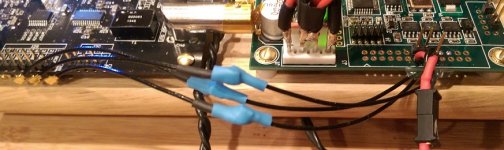
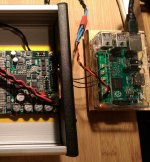
I added u.fl sockets on the bottom of the I2S headers... then use short male-female u.fl cables to match to the u.fl cable pigtails I soldered onto the DAM isolated I2S inputs... see attached pix.
I also included a picture of my R-Pi->DAM setup... it uses Ian's R-Pi adapter, so also fed via u.fl.
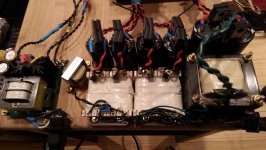
I have a number of power supply & output stage upgrades planned, but darn it, the thing sounds so good right now that it is sapping my will to do any of these! I am using a fairly high 13.5v+- input to the currently stock DAM right now, these are fed from a supply with good quality over-spec'd fast recovery diodes and 47,000uf Jensen 4-pole caps per rail.
I plan to do the upgrades in a fairly measured way, on one, then the other, so I can have some point of reference for each. I've done what I expected to be upgrades on other gear in the past that were not, so I try to do them in a way that allows me to assess and regroup if needed.
Battery power is on the menu as one of the last courses, but I'm trying to get them to sound as good as I can with AC-sourced supplies first.
Greg in Mississippi
P.S. The 9 different supply rails are not all used right now, but will all be used as I upgrade the power networks. Note that the supply diodes and caps by themselves cost about 2x that of a DAM board, but I believe that one's power can never be too good!
Attachments

Last edited:
If tried a few i2s sources and they all sound different so......
The first thing to check would be to see if the I2S data coming from these sources is really identical. I mean not just the software setup which "should" produce bit perfect playback, but the actual electrical signal on the wire.
There may also be differences in noise , slew rate and ringing of the I2S signal and in noise of the isolator power. If some differences can be seen on the other side of the isolators, and there is a correlation between what is measured on each side of the isolators, it would explain some of these observations.
Verifying the actual recklocking using a black box approach could be a little tricky. One interesting test might be to use a function generator for the I2S mclk source and to frequency modulate it with various signals, not changing anything else in the setup. If the reclocking works as advertised, sound should be indistinguishable in all cases.
well i was just hinting at the possibility that upstream will always affect downstream to a certain extent and there might be no magic bullet or fix all
board damaged
Today I did the Vref mod on my v1 board, removed 4 opamps as well, unfortunately it's not a success, one channel is fine, another channel, with lots background static noise, the sound is weak and seems lost focus, any idea what could be the problem? fixable?
Thanks
Today I did the Vref mod on my v1 board, removed 4 opamps as well, unfortunately it's not a success, one channel is fine, another channel, with lots background static noise, the sound is weak and seems lost focus, any idea what could be the problem? fixable?
Thanks
Today I did the Vref mod on my v1 board, removed 4 opamps as well, unfortunately it's not a success, one channel is fine, another channel, with lots background static noise, the sound is weak and seems lost focus, any idea what could be the problem? fixable?
Thanks
check vref voltage levels
could be anything from a dead or dying 4v reg to a blob of solder causing a short somewhere
good chance its fixable
pics might help
Last edited:
- Home
- Vendor's Bazaar
- Reference DAC Module - Discrete R-2R Sign Magnitude 24 bit 384 KHz