The same problem with random delays in acquiring lock among the boards exist in your case. An official answer from Soren is probably needed.
You would have the peace of mind if you could work with dam1121, but it requires more work and is more fragile.
Yes, exactly my concerns. Soren said originally that it would work, which is why I went ahead and ordered 4 boards. There was a manual promised which I expected to address the issue. All we have been told is to split the signal between the boards. No subsequent confirmation anywhere that it actually works. Before I actually spend all the money on all the power supplies, etc. and all the time to put it together, I would like to know if it will work as promised without delay and other issues.
Yes, exactly my concerns. Soren said originally that it would work, which is why I went ahead and ordered 4 boards. There was a manual promised which I expected to address the issue. All we have been told is to split the signal between the boards. No subsequent confirmation anywhere that it actually works. Before I actually spend all the money on all the power supplies, etc. and all the time to put it together, I would like to know if it will work as promised without delay and other issues.
If you have the 1121 I'm certain you could sync them using one clock internal or external. If you have the 1021, I did see somewhere Soren comment that it will have a max of several micro seconds in delay. He has not commented since.
Practically speaking, if you're using speakers in dual-mono, I don't see a problem with a few us of delay (mm in phase difference). But if you're using 4 channels (not sure why you would do that but anyways...), you need to consider the impact of the us level delay. If you're stacking 2 boards per channel in a balanced build, that could be a large problem imho.
I have 2 boards and am looking for an answer too...
Why would you stack 2 boards for 1 channel?
//
To copy MSB and totaldac's approach? Increase SNR the old fashioned way - spend more money...... It also has the added benefit of decreased output impedance. So if one stack, say, 3 ladders per signal channel (Totaldac d1 12?), you would get a third of the output impedance 🙂 At some point you would not need a buffer any more, like MSB...
Also, I went through a lot more posts than I thought existed and found crazy mods like this: Soekris DAC with comprehensive guide on how to remove everything on the dam1021 and replace it with batteries instead...
And this: Сергей Шалаев - Моя поделка.
На выходных запустили мою... | Facebook Russians win...
So perhaps I was wrong about 2 board per channel not feasible with dam1021...
Last edited:
Multiple boards: The dam1121 can be connected synchronous, the dam1021 can be connected asynchronous, but will sync to within a few uS, not something you can hear.
Fully Balanced: Can be used for the dam1021 and dam1121, a mode setting in uManager on dam1021 and a hardware setting on dam1121. Several people have done that successfully, search thread for details.
Paralleling multiple boards: Easy with the dam1121, probably fine with dam1021 unbuffered, not recommended using the dam1021 buffers.
As crossover: the dam1021/dam1121 have the hardware with support for up to 15 IIR biquad filters per board. How to do it is an advanced DIY project, not something I will provide support for. Probably much easier using a DSP....
Last edited:
After some more browsing... it seems that spikestabber had a similar question of whether to bridge the buffered outs in balanced mode. He resorted to a discrete head-amp board but the question is still relevant...
I'm guessing that bridging/paralleling the 2 signals of the same polarity would not introduce more noise. Quite the opposite, the noise from each signal would find its opposite in the other channel, canceling each other out. There might also be minor SNR improvements although the opamp buffer has no doubt deteriorated the signal to begin with...
----------------------------------------------------------------
On a completely different note, I also became a bit worried over how the dam1021 is powered by default due to the lack of a full understanding...
The digital parts, e.g. FPGA, oscillator, (?), are powered by the positive rail, whereas the opamps in the vref and the opamps in the buffer stage use both positive and negative rails. My worry stems from the common belief that digital and analogue must not share power source for best performance (perhaps to reduce noise interference in between the two?). After seeing that dam1121 offers three power in: 5V digital x2, and 5V analogue, I became more worried that a single set of DC input is insufficient even for folks who aren't going all out with batteries and external regulators.
Therefore, the questions are: (1) do we need separation of power source in this system (2) if we do, how can we mod the board to meet the requirements. If we still plan on using the opamp buffers (like I do..) we would need to keep the two rails powered as it is, without skipping to after the 5V regs perhaps. Then how are we to separate the digital power from the two rails?...
We could always go this route: randytsuch's audio page: Soekris R2R Dam Dac - Modding and forget about separation as we would basically have an independent power source for every major component... but short of that, do we have options?
------------------------------------------------------------
Also, Soren did say with high if not absolute certainty that the vref on the V4 boards is better than any external regulators. If this were true, and I tend to believe Soren's judgement here, then what else can we really plausibly improve on the dam1021 with our caps and regs? I noticed that spikestabber reported noticeable improvement in bass clarity etc. with A-B tests on the 3.3V reg upgrade for the oscillator. Is there a contradiction here or is there only the appearance of one?
Again any comments/discussions would be very helpful.
Multiple boards: The dam1121 can be connected synchronous, the dam1021 can be connected asynchronous, but will sync to within a few uS, not something you can hear.
Fully Balanced: Can be used for the dam1021 and dam1121, a mode setting in uManager on dam1021 and a hardware setting on dam1121. Several people have done that successfully, search thread for details.
Paralleling multiple boards: Easy with the dam1121, probably fine with dam1021 unbuffered, not recommended using the dam1021 buffers.
As crossover: the dam1021/dam1121 have the hardware with support for up to 15 IIR biquad filters per board. How to do it is an advanced DIY project, not something I will provide support for. Probably much easier using a DSP....
Thanks and great to hear from you again Soren! I'll just use 2 dam1021 asynchronously and forget about the delay 🙂
In terms of paralleling, I understand that more than 2 boards would not be ideal for dam1021, but would paralleling the buffered outputs in a fully balanced setup be a good idea in terms of noise and output impedance? I.e. positive from BAL-L board left channel paralleled with negative from BAL-L board right channel to power headphones?
Thanks again!
As I said, not recommended paralleling using the dam1021 buffers.
The levels are set by a 0.5% reference and a number of 0.5% resistors, so the voltage levels might have a too large difference to just parallel the output buffer, even as the buffer have those 10R series resistors.
The noise is already very very low.
Thanks! I would definitely not want to short my boards this way... This really put an end to the age-old discussion!
Just a quick question while you're here, how much of an improvement would a fully discrete solid state pre-amp / head-amp be over the 0.5% parts used currently...? And could we expect such a fine add-on to be coming soon?...
Also, any comments on the digital/analogue separation in dam1021?...
Thanks for the great product as is!
As crossover: the dam1021/dam1121 have the hardware with support for up to 15 IIR biquad filters per board. How to do it is an advanced DIY project, not something I will provide support for. Probably much easier using a DSP....
Is all the information/prerequisites described in the manuals to really pull this off?
//
Thanks! I would definitely not want to short my boards this way... This really put an end to the age-old discussion!
Just a quick question while you're here, how much of an improvement would a fully discrete solid state pre-amp / head-amp be over the 0.5% parts used currently...? And could we expect such a fine add-on to be coming soon?...
Also, any comments on the digital/analogue separation in dam1021?...
Thanks for the great product as is!
The used opamps are good, a good discrete amplifier will be better but it will of course depend on how good it is....
As I mentioned before, I actually have a prototype here of a discrete amplifier, had some problems with ultra low frequency noise, not something you can hear but something you can measure. Couldn't remove it complete, but now have it under control. The final version basically ended up in the dac1541.... Might offer it at some point, but don't know when.
The dam1021 analog power is basically filtered by a CRC network, I believe it's fine, other people want other power solutions....
The used opamps are good, a good discrete amplifier will be better but it will of course depend on how good it is....
As I mentioned before, I actually have a prototype here of a discrete amplifier, had some problems with ultra low frequency noise, not something you can hear but something you can measure. Couldn't remove it complete, but now have it under control. The final version basically ended up in the dac1541.... Might offer it at some point, but don't know when....
Yes, please! Think that’d be of interest to enough folks to make it worth your while.
On another topic - any progress on a replacement U.S store?
Happy New Year!
The used opamps are good, a good discrete amplifier will be better but it will of course depend on how good it is....
As I mentioned before, I actually have a prototype here of a discrete amplifier, had some problems with ultra low frequency noise, not something you can hear but something you can measure. Couldn't remove it complete, but now have it under control. The final version basically ended up in the dac1541.... Might offer it at some point, but don't know when.
The dam1021 analog power is basically filtered by a CRC network, I believe it's fine, other people want other power solutions....
Also looking forward to the release of the head-amp! I would definitely get one if it can be stacked on the dam1021...would be even better if it’s offered in balanced setup and easy to integrate with existing power supplies for the dam1021 (e.g. same +-9V or 12V DC supplies if that’s good enough..) ! A US distributor will certainly help as well!
I have a couple more questions:
(1) Are the ground returns for digital and analog isolated, at least with a 0R resistor? If not can you explain why it isn’t needed? It would be nice to know for sure that we’re not missing out too much not using batteries...
(2) If you’re right and that the CRC filtering provides clean enough analog power rails, and I guess this is partly corroborated by the lack of improvement in providing externally regulated 5V DC directly to the vrefs, power-wise I now see a few more options:
a. Bypass main regulators and provide +-5V DC(?) directly. Based on reported experiments, this doesn’t seem to power the entire board, at least the muting circuits properly. Also, please correct me if I’m wrong, I’m not sure if anyone reported meaningful improvements..
b1. Bypass the 3.3V regulator for the oscillator (and perhaps the FPGA?) and use a quality external regulator, such as NewClassD, Sparko or muzgDIY. Multiple reports of improvements can be found in this thread.
b2. Supply externally regulated (or battery powered) 3.3V DC to the rail. Only reported attempt seems to be with batteries by randytsuch (in his blog) and other battery tweakers. Not sure how this compares to the off board regulator approach.
c. Bypass 1.2V regulator for the vref switches. Again this seems to be done only with batteries and little improvement was reported.
Did I miss anything? Can I understand the power regulation onboard as:
AC/DC -> main regulators -> +-5V DC
+5V DC -> 3.3V reg -> Digitals (FPGA and oscillator) -> 1.2V reg -> vref switches
+-5V DC -> 4V reg -> vref
+-5V DC -> buffer op-amps
Where does the muting circuit fit in? Where is it supposed to draw 6V DC from?..
Thanks for your input and everyone else’s here as we advance towards the best sounding dam1021 setup that’s also easily accessible to all!
It's amazing how little I actually know about the DAM DAC... There's just so much hidden in the electrical circuits and components that could affect the performance, completely hidden away from non-majors behind the pretty abstractions... Let alone the fact that we don't really know the full dam1021 schematics...
I found out after studying all 77 pages of Soekris Dam Dac - Tir Na HiFi where Nigel and friends went for (and got VERY far) the ultimate dam1021, destroying a few boards now and then of course.
First of all, correcting my last post, the power regulation on the dam1021 is more likely:
AC/DC -> Bridge rectifier -> PWR A+/-
PWR A+ -> 3.3V Regulators-> Digitals (FPGA, oscillator and microprocessor)
PWR A+ -> 1.2V Regulator -> ?
PWR A+/- -> +/-5V Regulator -> +/- 5V DC -> Op-amps -> 4V vref -> shift registers
PWR A+/- -> Output buffer op-amps
[Probably still missing some but better than last...]
With this, now I can answer my own questions...:
(1) Digital/analog separation in the ground plane, or power in general, is probably not perfect. There is no conclusive evidence but the fact that Nigel and friends believe the vref battery mod was the most significant among all the mods which they A/B tested gives some hint. The mod basically provides independent power supply to the analog circuits (with output buffer already removed...).
(2) One could go all out on battery/externally regulated power supplies for all voltages/major components on-board, as a few did. And replace the 1.2V switch-mode regulator which seems to be noisy by an LDO counterpart... Here's my current idea of a reasonable and accessible mod, if the output buffer is not needed:
i. Supply PWR A+ with 5-7V DC, replace 3.3V regulator with Sparko discrete regulator, wire the VCC on the oscillator directly to the regulator for improved performance.
ii. Replace 1.2V switch-mode regulator with LDO.
iii. Supply ~4V (such as 3.3V with LiFePo4 battery) to shift registers, bypass op-amps. If done with batteries capacitors can be left out, but if done with (here I'm very much not sure...) regulators, supercapcitors might be needed. A possible regulated supply is perhaps Regulated DC -> 4* 4V Sparko Regulators. Sparkos are rated at 3uV ripple, 1.5% voltage precision, and 1A output, which should be enough for the shift registers (??).
iv. Supply future Soekris add-on buffer/headphone amp with the same regulated DC as the Sparkos for the shift registers. Or use an existing buffer kit.
v. (optional?) Swap out certain on-board ceramics for better caps / bridge more caps at places if there's room.
This should provide a higher level of digital/analog separation, better regulated voltage for critical components, and doesn't go as far as using battery supplies. Ideally, this should only require one transformer with two sets of secondaries for digital and analog respectively. one dual-rail linear regulator for analog and one single-rail linear regulator for digital. The enclosure would also have a quality buffer/head-amp built-in.
Does this sound reasonable? If so I might consider doing it next year when I have more time... also ideally after Soren releases the head-amp board so I can stack it with the balanced dam1021's....
This is just a naïve attempt at a decent mod... please offer critiques of any kind!
Happy New Year!
As a summary to my last post, the proposed setup would be along the lines of:
Transformer AC 15V -> Dual-rail quality regulator 12V -> buffer/head-amp board
-> +/-5V DC-DC quality regulator -> onboard 5V (then 4V opamp regs -> shift reg)
[OR -> +/- 4V extremely high quality regulator -> shift regs]
-> Single-rail quality 5V regulator -> PWR A+ -> Sparko 3.3V reg to replace onboard reg (or similar) -> all digitals
-> 1.2V LDO reg to replace onboard switch mode reg -> something....
One would also need to remove the onboard buffer circuits, main filter caps, bridge rectifier and 5V regs.
The problem here without using batteries is the feasibility of providing accurate enough 4V vref and the performance of compromising and only feed +-5V dc to the onboard opamps.
The current vref + and - rails track to 0.01% according to Soren, and a 0.1% difference would result in 12dB increase in second harmonics. So providing two rails of 4V accurately enough is at least something to worry about. Could we do meaningfully better than the onboard opamp approach without LiFePO4, I.e. external voltage regs? If not, it would still be nice to know that the Soekris approach is only second to batteries.
This is somewhat beyond what I can find out with google searches effectively. Some expert input would be greatly appreciated. In any case, I’ll try to document what I’ve found out soon to provide a starting point for the more knowledgeable that may stumble upon this great DAC!
Thanks!!
P.S. as i typed this up it occurred to me that Soren said the vref is already better than any external regs.... still would be nice to have some confirmation since significant improvement was reported by using batteries to provide vref.
P.P.S. The formatting of the first part seems off... attached a screenshot of what I meant..
Attachments

Last edited:
Happy new year to everybody! 
I finally finished going through the 684 (!!!) pages of this thread during my Christmas holiday! 😛
I started reading this thread already a year or two ago at a time where the dam1021 board received still quite some complaints, but I finally decided to go for this platform after reading the much more enthusiastic recent reactions...
I currently use the MHDT Paradisea DAC (Philips TDA1545 with tube buffer) with USB connection to PC, two Ncore mono-block amps and Supravox 8" Bicone based open baffles. I would like to try a more modern DAC now. I appreciate the higher maximal sample rate, higher bit depth, lower jitter and especially the possibility for low loss digital volume control of the DAM design!
I ordered a dam1021-12 and the advised optical TORX receiver and 1:1 S/P-DIF Murata transformer. I plan to start very simple with off-my-shelf components (2x15V toroid with LM7812/7912) and optical an/or coaxial S/P-DIF.
Later on, I plan to upgrade to low-noise supplies (using a toroid with lower voltage naturally) and an XMOS 384k USB board. I may even consider to go for the multi-channel board. Long term it would be great to do a crossover using PC or onboard filtering.
Anyhow, I really look forward to try this beast out! 🙄
I could imagine a workaround for loss of bit exactness due to the requirement of lower than 1 multipliers. Try a multiplier of 0.5. This would result in a (signed) right shift of exactly one bit which can be exactly compensated by applying a factor of two (more) digital gain. You will lose one LSB of intermediate internal precision, but given the long internal word lengths I expect this to have no impact. Question of course is whether this change for bit exactness would bring any audible improvement at all...
@Soren
If the first step of filtering/signal processing is done by the computer, it would be nice to have the following features in a future firmware. Would this make too much trouble?
1.) For 352.8, 384 Ksps an (optional) real bypass of FIR1.
I.e. that the bits sent will be the input of FIR2 (if the volume is set to 0dB). Currently this is not the case due to the multiplicator (that can not be set 1) and possibly due to the DC blocking filter and the De-emphasis.
Last edited:
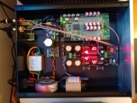
Hey guys, I'm a bit out of the loop. I built the dam1021 two years ago, I believe it's a rev2 board. See post #864 here: http://www.diyaudio.com/forums/digi...ekris-dac-implementations-18.html#post4569955
I did the Vref mod with polymer caps as can be seen in post #4603 here: http://www.diyaudio.com/forums/vend...-magnitude-24-bit-384-khz-93.html#post4617043
I have a rev4 from the xmas special on the way and was wondering what mods have proven worthy of implementing. From what I've read the Vref mod is not as crucial anymore, but I still have a bag of those fpcap polymers from back then, so I guess I'll install them just because.
Anything else? Maybe polymer caps at the output of the Vref generating chips? Filters? My rev2 is still equipped with the stock FW and filters, maybe I should update these as well. Like I said, I'm a bit out of the loop here...
Attachments
I could imagine a workaround for loss of bit exactness due to the requirement of lower than 1 multipliers. Try a multiplier of 0.5. This would result in a (signed) right shift of exactly one bit which can be exactly compensated by applying a factor of two (more) digital gain. You will lose one LSB of intermediate internal precision, but given the long internal word lengths I expect this to have no impact. Question of course is whether this change for bit exactness would bring any audible improvement at all...
The problem is that the gain is set in dB so you do not get an exact factor 2 this way.
For listening it probably does not matter, but for some measurements control of the actually set bits can matter.
As a summary to my last post, the proposed setup would be along the lines of:
Transformer AC 15V -> Dual-rail quality regulator 12V -> buffer/head-amp board
-> +/-5V DC-DC quality regulator -> onboard 5V (then 4V opamp regs -> shift reg)
[OR -> +/- 4V extremely high quality regulator -> shift regs]
-> Single-rail quality 5V regulator -> PWR A+ -> Sparko 3.3V reg to replace onboard reg (or similar) -> all digitals
-> 1.2V LDO reg to replace onboard switch mode reg -> something....
One would also need to remove the onboard buffer circuits, main filter caps, bridge rectifier and 5V regs.
The problem here without using batteries is the feasibility of providing accurate enough 4V vref and the performance of compromising and only feed +-5V dc to the onboard opamps.
The current vref + and - rails track to 0.01% according to Soren, and a 0.1% difference would result in 12dB increase in second harmonics. So providing two rails of 4V accurately enough is at least something to worry about. Could we do meaningfully better than the onboard opamp approach without LiFePO4, I.e. external voltage regs? If not, it would still be nice to know that the Soekris approach is only second to batteries.
This is somewhat beyond what I can find out with google searches effectively. Some expert input would be greatly appreciated. In any case, I’ll try to document what I’ve found out soon to provide a starting point for the more knowledgeable that may stumble upon this great DAC!
Thanks!!
P.S. as i typed this up it occurred to me that Soren said the vref is already better than any external regs.... still would be nice to have some confirmation since significant improvement was reported by using batteries to provide vref.
P.P.S. The formatting of the first part seems off... attached a screenshot of what I meant..
I don't know anyone that actually compared a properly implemented vref circuit to a good external voltage regulator to lifepo4 batteries. I never did, I went from the very original (flawed) vref circuit to lifepo4 and never felt the need to try anything else. IMHO, it was better, but I don't know how it would compare a modified vref circuit. I have one of the original dac's, so a vref mod was required for the best sound, it's well documented in this thread. Vref was fixed in the later revisions of this dac.
From what I remember, vref and the power to the isolated section made the most difference to sound, but obviously ymmv.
- Home
- Vendor's Bazaar
- Reference DAC Module - Discrete R-2R Sign Magnitude 24 bit 384 KHz