Powercycling both.Are you power cycling the DAM or the RPi (or both)?
Have you prevented linux from using the serial port?
Thanks - I dont think I have prevented the OS from using the serial port.
It might be the cause?
Using latest picoreplayer. Its based on tinycore linux which is not like other distros.
There are noen /boot folder or any traces of cmdline.txt where I can disable
setting. I am stuck trying to find the right place to change this.console=ttyAMA0, 115200
I have now asked the tiny core community.
EDIT: Found it. The folder where cmdline.txt is store gets unmounted at boot. Remount and the files where all there. Made the changes and made it persistent. Now - no "garbage" gets piped to /dev/ttyAMA0
But - my mind is making tricks on me. I actualle feels it sounds a bit more open? Is it a logical reason for this or am I just imagine it? My bet is the imagine 🙂
Last edited:
this is my input voltage +/- 15V
An externally hosted image should be here but it was not working when we last tested it.
Why 15V? It will generate a lot of heat or even blow the circuit.
Datasheet: preferable 9-12V DC
Try 9V, less heat, less stress.
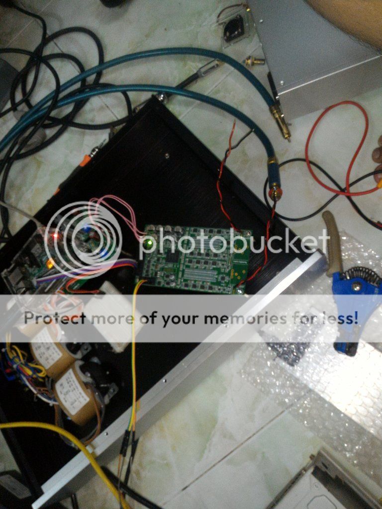
Hi and thanks for your input, please follow my pictures because I made some new measurements, and maybe you'll be able
to point me out in the right direction with some measurements made an a working board to be able to localize my problem
this is my input voltage +/- 15V
THIS IS MEASURED ON THE 3,3V LDO input
this is the ohm-meter pins in short
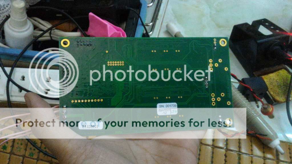
and this is the 3,3v LDO's output - it seems like it's in short-circuit although the traces are fine
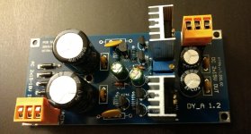
this is the way I tied up my potentiometer having the GND connection in the middle
and this is the initial original picture which guided me for the potentiometer connection with the observation
that there is not noted on the pot side where is it's GND (on mine it was in the middle)
and this is the way it was tied to the board when suddenly the 3,3v LDO was blown away; also the LED lamp on the board does not light up
any information is welcome... maybe Soren could tell me if the FPGA could be replaced with a new one in case it is also damaged and what would be the cost?
First we need to establish exactly why it died, as I said before the 3.3V regulator is good protected so a short by itself will not kill anything....
How exactly was the board powered, you earlier mentioned 20V ??
A short is always hard to locate, a trick is to apply a very low voltage high current power to the 3.3V plane and then look for the place with lowest voltage on it....
You can of course replace any parts, but replacing the FPGA would probably cost more than a new board once you include all cost....
Hi and thanks for your input, please follow my pictures because I made some new measurements, and maybe you'll be able
to point me out in the right direction with some measurements made an a working board to be able to localize my problem
this is my input voltage +/- 1
....
and this is the initial original picture which guided me for the potentiometer connection with the observation
that there is not noted on the pot side where is it's GND (on mine it was in the
.....
and this is the way it was tied to the board when suddenly the 3,3v LDO was blown away; also the LED lamp on the board does not light up
'.........
any information is welcome... maybe Soren could tell me if the FPGA could be replaced with a new one in case it is also damaged and what would be the cost?
FYI; I had an issue with the 3.3v ldo supply also; I had a short on the 3.3v. I was able to trace the fault component with a lab power supply; Limit the v/i, and apply for a short time. The short component heats up quickly, sense it with fingertips..... In my case only the stm 32 cpu was gone, after replacing it the board was ok.
I replaced the ldo also, but that was not necessary.
Why 15V? It will generate a lot of heat or even blow the circuit.
Datasheet: preferable 9-12V DC
Try 9V, less heat, less stress.
I've ran mine at +-15V for months on the stock LDO with no ill effects, the LDO got quite warm but nothing near its limit. I've since went 12V simply because it runs the Sparko 3.3V regulators a good 15C cooler, they run stupidly hot otherwise.
I finally got my rev1 boards and I can begin with them after I'll get regulators for power supply. I've been studying about vref modifications and I've also been thinking of using battery power supplies so I've some questions about it. Which parts need +- voltage? If I remove buffers and use +-4V for vref is there anything else that needs +-V?
And then what is the absolute limit for vref voltage? If I use 3,7V batteries they need to be charged with 4,2V. Is that too much or should I disconnect batteries with relay during charging them? It would be possible to switch to regulators during charging or use two batteries and switch between them. Should not be too difficult to do that.
And then what is the absolute limit for vref voltage? If I use 3,7V batteries they need to be charged with 4,2V. Is that too much or should I disconnect batteries with relay during charging them? It would be possible to switch to regulators during charging or use two batteries and switch between them. Should not be too difficult to do that.
So mine build.. i think one of the "plan minimum" - as i sow from few other builds on this site..
Only additional capacitors added (rev3 board)

Since last post none of loosing sync issue - so build is stable..
i2s from orange pi works up to 384khz..
i install on orange pi openelac+kodi.. because i have already kodi and it is easy to use one apk. as remote controller


Only additional capacitors added (rev3 board)
Since last post none of loosing sync issue - so build is stable..
i2s from orange pi works up to 384khz..
i install on orange pi openelac+kodi.. because i have already kodi and it is easy to use one apk. as remote controller
Check before powering up!
Hi Forum,
Being a little confused as to the power supply connections, I have annotated the appropriate diagram from the user manual and wondered if people could comment as to whether I am correct?
I would welcome any comments regarding whether an AC input or the regulated DC input from the board (attached / D1762) I am thinking of using would be 'best' please?
Many thanks!
Attachments


Last edited:
please look at:
https://hifiduino.wordpress.com/2015/03/16/soekris-dam-1021-r-2r-dac-users-guide/
It's shown both options.. in mine case with only transformer i heave loosing sync issue..
https://hifiduino.wordpress.com/2015/03/16/soekris-dam-1021-r-2r-dac-users-guide/
It's shown both options.. in mine case with only transformer i heave loosing sync issue..
Going to try a Singxer C-1 (XU208+reclocker) in place of the Amanero myself, really wanting to see if there is a difference like many have observed...
Had a chance to install it and listen the last few days.
Seriously, the newer XMOS based converters are no joke. I thought it was merely subjective but its anything but. One could say its like cleaning a window and considerably more laid back sounding. Even things that used to overpower the sound, ie, heavy thrash metal are considerably more detailed. If anyone is still using an Amanero its time to upgrade it. The dam1021 *does* greatly benefit despite having its own reclocker.
I can only guess its because the initial conversion from USB is superior on the newer XMOS chips, which is in-line with what many others here and elsewhere have said. The Singxer C1 is pretty much an F1 without the active isolation for those wondering. I'd imagine the DIYINHK XU216 board will produce the same results, it looks to just use the other tile for the same purpose as the extra CPLD on the Singxer.
Anyone else have a similar experience?
.... I thought it was merely subjective but its anything but. ..
So objectively... how is it?
//
The new 1231 hat board for Raspberry Pi looked like it would have 4 inputs. How do you switch between them?
Hi, sort of "bumping" this.Hi, back to new firmware possibilities.
Is it possible to get a firmware where it is not possible to adjust to +10dB? I have yet to find music where this is necessary. Every tune gets distorted.
0dB is more than enough 🙂
Asking for a firmware adjustment where this +10dB setting from volume kan be either adjusted to 0dB or fixed?
Best regards.
Had a chance to install it and listen the last few days.
Seriously, the newer XMOS based converters are no joke. I thought it was merely subjective but its anything but. One could say its like cleaning a window and considerably more laid back sounding. Even things that used to overpower the sound, ie, heavy thrash metal are considerably more detailed. If anyone is still using an Amanero its time to upgrade it. The dam1021 *does* greatly benefit despite having its own reclocker.
I can only guess its because the initial conversion from USB is superior on the newer XMOS chips, which is in-line with what many others here and elsewhere have said. The Singxer C1 is pretty much an F1 without the active isolation for those wondering. I'd imagine the DIYINHK XU216 board will produce the same results, it looks to just use the other tile for the same purpose as the extra CPLD on the Singxer.
Anyone else have a similar experience?
FWIW: I have the latest Gustard U12 (with Accusilicon clocks) which I've modded the hell out of. It has the former generation XMOS U8 chip and still it was a significant upgrade to the on board USB receiver on my totaldac. The totaldac also has a FIFO reclocker.
So I think you might be on to something. At $140 I think it's a no-brainer.
i buy it from soekris.eu. I received dam1021 today.but when i test with raspiberry pi 3. Board is locked but no sound. I changed buf and raw both no sound.please help me thank you!
Please help me! I very sad, I do not know who to contact now 🙁
Please help me! I very sad, I do not know who to contact now 🙁
Please Help Me, My Board no sound 🙁 i use 12v dc dual + raspberry pi 3 i2s with moodeaudio. signal is lock but still no sound 🙁
So objectively... how is it?
//
Imaging is noticeably more consistent, before it felt like it was all over the place, good at times, worse at times. It's possible the power quality to the Amanero matters a lot more than it does to the Singxer, but it's not something I actually dove into before.
i buy it from soekris.eu. I received dam1021 today.but when i test with raspiberry pi 3. Board is locked but no sound. I changed buf and raw both no sound.please help me thank you!
Please help me! I very sad, I do not know who to contact now 🙁
1) Check all I2S cabling. You've probably already done it, but check again.
2) Make sure you are powering the "dirty" side of the DAM's isolator.
3) Make sure that your RPi is indeed outputting an I2S signal. Do you have some other I2S DAC (perhaps some HAT DAC) that you can use?
4) Do you have some other I2S source to try connecting to the DAM?
Had a chance to install it and listen the last few days.
Seriously, the newer XMOS based converters are no joke. I thought it was merely subjective but its anything but. One could say its like cleaning a window and considerably more laid back sounding. Even things that used to overpower the sound, ie, heavy thrash metal are considerably more detailed. If anyone is still using an Amanero its time to upgrade it. The dam1021 *does* greatly benefit despite having its own reclocker.
I can only guess its because the initial conversion from USB is superior on the newer XMOS chips, which is in-line with what many others here and elsewhere have said. The Singxer C1 is pretty much an F1 without the active isolation for those wondering. I'd imagine the DIYINHK XU216 board will produce the same results, it looks to just use the other tile for the same purpose as the extra CPLD on the Singxer.
Anyone else have a similar experience?
Is it possible to power the Singxer C1 externally like the Amanero or is USB VBUS the only way?
- Home
- Vendor's Bazaar
- Reference DAC Module - Discrete R-2R Sign Magnitude 24 bit 384 KHz