Soren,
I see the rev 3 boards listed as on stock in the shop, but still using the image of the prototype board.
Could you please, at least here, post an actual image of the rev 3 board.
I have two DAM1021 rev. 3.0 on order, would be happy to post pictures when they arrive.
1) There is absolutely no reason the bypass the isolators, all the digital signals get reclocked anyway in the FPGA.
2) The isolators are Silicon Labs SI8620BB-B-ISR, take a look at the datasheet to understand how they work....
I am sure those things have their place in the world.
WAVE IO has a choice of isolated and non-isolated outputs. There is a sonic difference between the two. It seems everyone admits these things do add "jitter". When connected to the average computer they are worthwhile but if the isolation is not needed they do get in the way. Needless to say I will not be using WAVE IO any longer but use it as a reference point
I used a four volts battery to power mine - thought that would split the difference. Seems there was a slight bettering of stated performance with five volts versus 3.3 but a five volts battery is not (easily) possible so I went with four volts which is easy to come by.
The funny thing is the sonic difference with and without powering was very small to the point I wondered if I heard any difference at all but then my computer setup was not typical. In fact it was such a pain that that is the reason I am not going to use one anymore.
There is no question the SDTrans does not require this isolation.
I am sure those things have their place in the world.
WAVE IO has a choice of isolated and non-isolated outputs. There is a sonic difference between the two. It seems everyone admits these things do add "jitter". When connected to the average computer they are worthwhile but if the isolation is not needed they do get in the way. Needless to say I will not be using WAVE IO any longer but use it as a reference point
Of course the isolators add jitter, it's even in the datasheet. And it will affect any normal DAC chip which are not reclocking or don't have a reclocking FIFO....
Last edited:
I guess I see it conceptually - reminds me of HUMPTY DUMPTY - I worry, as I do with FLAC files, that once "broken" there is no assurance that what we do afterwards will put all back together as it was.
This might well be fanciful (and as childish as the tale) but there are numerous times in analogous situations where something is detected as missing.
Please do not take my modifications as a comment on your design - far from it - you have produced something which can satisfy many at an excellent price. I am compelled to find ways to make it better for my situation. At least, I think it is better! Nothing better than an effective placebo, every bit as good as the real thing!
‘’Please do not take my modifications as a comment on your design - far from it - you have produced something which can satisfy many at an excellent price. I am compelled to find ways to make it better for my situation. At least, I think it is better! Nothing better than an effective placebo, every bit as good as the real thing!’’
Well said Rick
I’ve been surprised how good this DAC sounds un-modded and makes a good starting point for tweaking a little more out.
I’ll be starting my own journey once I’ve had a play with the filter settings.
I like your work with batteries.😎
But it’s sounding pretty good ATM
Well said Rick
I’ve been surprised how good this DAC sounds un-modded and makes a good starting point for tweaking a little more out.
I’ll be starting my own journey once I’ve had a play with the filter settings.
I like your work with batteries.😎
But it’s sounding pretty good ATM
And it's a fair point.😎
Your DAC sounds very good as is and well worth the cost.
BTW I have a pretty basic ''get me started'' PSU set up ATM.
WAVE IO/TP Teleporter, 317/337 linear/TPS7A4700 based reg for the ISO.
Sounds good.🙂
One of the things that's really impressive about the DAM to my ears is its lack of ''glare''.
good work
if I change anything then the risk is mine.
Battery supply to resistors
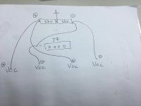
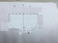
For battery supply, I bought 4nos of 3.7v rechargeable batteries and going to attach a battery box on top of chassis. 4nos of 3.7v batteries will be connected in parallel. I am going to connect all the 16 nos of vref of resistors like the photo shown. Can someone kindly tell whether correct?!
Also if the original 4v supply to resistor still connected to power up the resistor, will both power supplies will burn up the resistors?
Thanks
Comickitkit
Attachments
I like your work with batteries.😎
But it’s sounding pretty good ATM
I have followed the example of jkeny and nige2000 at TIR NA AUDIO - I can only take credit for, what I think is, a good implementation. The proof that it works and its value sonically is purely Nige2000's, the determined intrepid one.
The irony is using the batteries is much easier than trying to "perfect" the onboard Vref especially if you intend to add all of those capacitors.
I have had no close calls from the battery experiments. My board works just fine and is stable. I was very careful and appreciate SOEKRIS's many warnings since they kept me in check during the process.
I am completely happy with my SOEKRIS board and feel (almost) confident this is it for me. There would have to be a giant leap in performance to get me to change. And that leap would have to be reasonably priced and that is not likely.
I am not getting sound that equals my LP setup but it is better than any digital I have heard in my house.
I have high hopes with going to the SDTrans instead of the computer. I think the computer was holding the SOEKRIS back. Will not know for sure until the SD card player arrives. Of course, it will be powered with the same battery scheme as the DAC.
The SOEKRIS DAC is, by far, the best sensible DAC on the market. For those who want to spend silly money to eke out a little more, well, if I had it I probably would, too. THANKS to SOEKRIS for giving the rest of us something very good to work with.
For battery supply, I bought 4nos of 3.7v rechargeable batteries and going to attach a battery box on top of chassis. 4nos of 3.7v batteries will be connected in parallel. I am going to connect all the 16 nos of vref of resistors like the photo shown. Can someone kindly tell whether correct?!
Also if the original 4v supply to resistor still connected to power up the resistor, will both power supplies will burn up the resistors?
Thanks
Comickitkit
Attachments
I have followed the example of jkeny and nige2000 at TIR NA AUDIO - I can only take credit for, what I think is, a good implementation. The proof that it works and its value sonically is purely Nige2000's, the determined intrepid one.
The irony is using the batteries is much easier than trying to "perfect" the onboard Vref especially if you intend to add all of those capacitors.
I have had no close calls from the battery experiments. My board works just fine and is stable. I was very careful and appreciate SOEKRIS's many warnings since they kept me in check during the process.
I am completely happy with my SOEKRIS board and feel (almost) confident this is it for me. There would have to be a giant leap in performance to get me to change. And that leap would have to be reasonably priced and that is not likely.
I am not getting sound that equals my LP setup but it is better than any digital I have heard in my house.
I have high hopes with going to the SDTrans instead of the computer. I think the computer was holding the SOEKRIS back. Will not know for sure until the SD card player arrives. Of course, it will be powered with the same battery scheme as the DAC.
The SOEKRIS DAC is, by far, the best sensible DAC on the market. For those who want to spend silly money to eke out a little more, well, if I had it I probably would, too. THANKS to SOEKRIS for giving the rest of us something very good to work with.
I am going to use battery to replace the vref and direct feed into the shift reg. I've checked online about charging of lithium battery and it seems that charging IC should be used to prolong the battery life and for safe. In addition, I found that it is better to parallel multiple battery to yield better result.
So could you share with me the configuration that you did? I would like to parallel multiple battery, connected by relay when the dac is on, with another relay that connects to charging circuit when the dac is off and the charging circuit is on.
Thanks
For battery supply, I bought 4nos of 3.7v rechargeable batteries and going to attach a battery box on top of chassis. 4nos of 3.7v batteries will be connected in parallel. I am going to connect all the 16 nos of vref of resistors like the photo shown. Can someone kindly tell whether correct?!
Also if the original 4v supply to resistor still connected to power up the resistor, will both power supplies will burn up the resistors?
Thanks
Comickitkit
follow Randys blog
randytsuch's audio page: Soekris R2R Dam Dac - Modding
you need a switch on + and - vref
the polarity looks wrong on your diagram
if you get that wrong id very much doubt anything good will happen

wtf is that
besides a dac killer?
its a reasonably simple mod but very unforgiving for mistakes
please guys do your research
measure twice and cut once 🙂
everything is in randys blog or at tir na
be safe....
Last edited:
The key to the battery approach is not trying to charge the batteries after they have run down.
Use the battery as a capacitor with a regulator that is always on. I used a combination of a DDDAC 3.3 volts shunt reg for the front end (clock and FPGA, etc) and the mravica reg (also, in this VENDOR'S BAZAAR) - two positive regs sharing the ground for plus and minus - this approach gives me exactly the same voltage for both polarities.
This hybrid approach is just as good sonically and much easier to deal with - you can set your batteries into place and leave them there. The batteries suffer no stress.
I would highly recommend the A123 26650 battery. Compliments of the USA taxpayers! They are more expensive but they are a known quantity. They have many fine qualities. Using something else would likely lead to disappointment.
I used a pair for each channel of the resistor stacks and a single to power the front end stuff. I used a BELLESON 1.2 volt reg for the FPGA. This is powered by the same battery that powers the clock.
Do not be concerned with using 4 volts for Vref. 3.3 volts is fine. The A123s are happiest at this voltage.
Here are some pictures of my implementation. As you will see I am not concerned about the beauty of my DAC. I leave it out in the open at all times.
here are some photos: Soekris DAC
The "switch" picture was taken before I realized that switching the grounds on an off would not work. I subsequently made the switch turn off the voltages.
The BIOS pictures are from my old computer set-up and I was too lazy to delete them this morning.
You will see the board has been cleared of all unnecessary components. There are no electrolytics and the only ceramics left are those for the clock and FPGA - to the right of the FPGA caps there are no caps remaining. The battery acting as a superior capacitor does not need those caps. Those caps mess things up acting as a non-linear spring for the voltage to the stacks. If you will forgive that analogy ...
The REGEN was subsequently battery powered after these photos were made per jkeny's advice. Now there will be no need for WAVE IO or the REGEN. (goodbye USB!)
I no longer use the onboard volume control and use a pair of Dave Slagle's autoformer attenuators at the output
I am re configuring the setup for use with SDTrans since none of that stuff will be needed.
Yes, I love balsa for my projects. Ultra low resonance and capacitance and easy to use.
Last edited:
Thanks Nige2000,
It is good to be a member here.
Can confirm all stuff before I make any disaster mistake
It is good to be a member here.
Can confirm all stuff before I make any disaster mistake
‘’I have high hopes with going to the SDTrans instead of the computer. I think the computer was holding the SOEKRIS back. Will not know for sure until the SD card player arrives. Of course, it will be powered with the same battery scheme as the DAC.’’
Hi Rick
Interesting
I’m using Jplay streamer ATM but always open to ideas.
The battery work really intrigues me so I’m planning on that path.
I’ve had a quick skim through Randy's blog (thanks) and will use the very good info found on it to start work.
I’ve also seen Nige’s work over on Tir Na and it’s interesting.
Batteries for me will be a new thing so I may well be back here for some tips later.
😎
You will see the board has been cleared of all unnecessary components. There are no electrolytics and the only ceramics left are those for the clock and FPGA - to the right of the FPGA caps there are no caps remaining. The battery acting as a superior capacitor does not need those caps. Those caps mess things up acting as a non-linear spring for the voltage to the stacks. If you will forgive that analogy ...
Eeeh, try putting a fast scope on the power pin directly on the LVC595's, you will will see some nasty switching noise.... You have the wires from the batteries acting as large inductors, those small ceramics on the power lines close to the LVC595's are very important....
Bypassing 101. 🙁
Totally agree. If you lack even the basic understanding of electronics, please do not start modifying something, the odds are stacked against you if you're looking to make improvements.
As for batteries? Really? Before you go down that route make sure you have bothered to look into battery noise, internal resistance and how well a battery holds its charge. I'll give you a hint; batteries operate by a chemical process, which is noisy by definition.
now youve done it rick
no bypass caps talk is red flag to a bull in most places
the text book says so
anyone knocking lifepo4s abilities obviously never carried out any experiments direct from cell
no bypass caps talk is red flag to a bull in most places
the text book says so
anyone knocking lifepo4s abilities obviously never carried out any experiments direct from cell
anyone knocking lifepo4s abilities obviously never carried out any experiments direct from cell
I've handled more LiFePo and LiPo batteries than I care to count, and rest assured that wasn't in a hobbyist capacity.
- Home
- Vendor's Bazaar
- Reference DAC Module - Discrete R-2R Sign Magnitude 24 bit 384 KHz