Note that +/-12V supply is unregulated. And some 10R resistor are in series with that (decoupled with electrolyctic cap at source and ceramic at opamps). These resistor will filter some ripple but reduce the voltage a little but some 9V is suffice to B1 buffer I believe. The best in this case is to power the DAM with stabilized PSU.Hi Soren Im thinking to add the B1 buffer circuit with LSK489 where the power is directly taken from the +12 and -12 Analog rails will that bear that load without issues?
PS.: 🙂 I love the idea to use the NP's B1 buffer in this DAC (is an elegant choice), for people using low impedance pre/amp (I use direct since my amp have high input impedance).
Late note: yesterday I made the DAM V0.99 update and worked! Today I can listen to
Last edited:
Details of next batch:
The next batch will of course have the factory vref modification with larger ceramic capacitors, but no electrolytic capacitors.
There will also be an improved mute circuit with jfet switches.
From next batch the lineup will be a 0.05% version (-05) and a combined 0.01/0.02% version (-12), need to not have too many versions and I couldn't really measure much difference between the -01 and -02.
The new -12 version will be priced between the old -01 and -02 versions, pricing will also go up a little on the -05.
----
Anybody want to add power on/off muting to existing ones can do that easily with a low power relay, like:
With latest firmware U37 pin 18 is now a "enable audio" signal, GND is mute, 3.3V is enable audio output. That pin can be connected to a mosfet or bipolar transistor with base resistor, then to a low power 5V (or 4.5V) DPDT non latching relay with protection diode, powered by VCC50 on J2. The relay should then short the audio outputs on J7 to GND when coil is not powered. Should be easily to biggy back on, especially if the XLR connectors are not mounted.
The 27K4 resistor also need to be mounted as that is used for early power fail detection.
Low power relay is defined as max 150 mW coil, plenty of small low cost signal relays available. Even better would be one of the ultra sensitive 50 mW coils....
Next batch will be the same physically.
Again I'm just waiting for the f****** last precision resistors to be able to mount the boards....
Do not wait please. Would welcome a board, where the R-2R resistors are not included. It would be a very nice mod adding my favorit resistors personally.
Preferring purchasing a board WITHOUT these resistors.
The filter bank switching is not (always) completely noiseless. The most audible faint "plops" I get when switching with Pauls ".99 party pack" from F4 to F7(NOS) at high volume. Perhaps some zero detect could also be added here. But that is not urgent, the noise is quite weak.
Hi Soekris, sorry to ask this, but I can't find on web the pinout of the DAC broad, which pin18 are you referring to? Thanks.
Details of next batch:
The next batch will of course have the factory vref modification with larger ceramic capacitors, but no electrolytic capacitors.
There will also be an improved mute circuit with jfet switches.
From next batch the lineup will be a 0.05% version (-05) and a combined 0.01/0.02% version (-12), need to not have too many versions and I couldn't really measure much difference between the -01 and -02.
The new -12 version will be priced between the old -01 and -02 versions, pricing will also go up a little on the -05.
----
Anybody want to add power on/off muting to existing ones can do that easily with a low power relay, like:
With latest firmware U37 pin 18 is now a "enable audio" signal, GND is mute, 3.3V is enable audio output. That pin can be connected to a mosfet or bipolar transistor with base resistor, then to a low power 5V (or 4.5V) DPDT non latching relay with protection diode, powered by VCC50 on J2. The relay should then short the audio outputs on J7 to GND when coil is not powered. Should be easily to biggy back on, especially if the XLR connectors are not mounted.
The 27K4 resistor also need to be mounted as that is used for early power fail detection.
Low power relay is defined as max 150 mW coil, plenty of small low cost signal relays available. Even better would be one of the ultra sensitive 50 mW coils....
I am not sure, is this the pin18 of U37?Hi Soekris, sorry to ask this, but I can't find on web the pinout of the DAC broad, which pin18 are you referring to? Thanks.
An externally hosted image should be here but it was not working when we last tested it.
Sorry, the above seems incorrect pin. It should be the one near J2.Hi Soekris, sorry to ask this, but I can't find on web the pinout of the DAC broad, which pin18 are you referring to? Thanks.
An externally hosted image should be here but it was not working when we last tested it.
Abra - whats your favorite resistor if I may ask?
//
The free choice of ladder resistors would be a nice feature IMHO,
because they are central part of the DAC. It has a few advantages:
1. Resistors can be paired and sorted by individual measurements. Technically speaking, you can achieve better results than using random selection.
2. You can use more powerful resistors (wattage), if you like this kind of mod.
3. You can select your resistors sound wise, to achieve objectively and/or subjectively better sound.
4. Diy people like to change the base product to add their own ideas.
Mod is really not my hobby, but sound is.
I see this project technically rather excellent, plus this is the most exciting audio project today.
But there is not enough possibility for people who think ohmic resistance and precision are not the only parameters to consider.
Anyhow, I would like to replace the es9018 digital part in my Lampizator DAC to hear how the academic excellence of a ladder DAC is converted into sound practice.
To answer your actual question too, my favorit Shinkoh tantalum resistors are totally inadequate for this project. They are not smd parts at all.
But I would like to experiment with smd tantalum film resistors.
Do not wait please. Would welcome a board, where the R-2R resistors are not included. It would be a very nice mod adding my favorit resistors personally.
Preferring purchasing a board WITHOUT these resistors.
I would be interested in such board too.
My favorite resistors are Z-Foil Texas Components Corporation
Regards,
tibi
Mod is really not my hobby
But I would like to experiment with smd tantalum film resistors.
I am looking forward to your manual soldering of a few hundred smd resistors. 🙂
I am looking forward to your manual soldering of a few hundred smd resistors. 🙂
With a hot air gun this can be done in few minutes.
Regards,
tibi
Anybody want to add power on/off muting to existing ones can do that easily with a low power relay, like:
With latest firmware U37 pin 18 is now a "enable audio" signal, GND is mute, 3.3V is enable audio output. That pin can be connected to a mosfet or bipolar transistor with base resistor, then to a low power 5V (or 4.5V) DPDT non latching relay with protection diode, powered by VCC50 on J2. The relay should then short the audio outputs on J7 to GND when coil is not powered. Should be easily to biggy back on, especially if the XLR connectors are not mounted.
The 27K4 resistor also need to be mounted as that is used for early power fail detection.
Low power relay is defined as max 150 mW coil, plenty of small low cost signal relays available. Even better would be one of the ultra sensitive 50 mW coils....
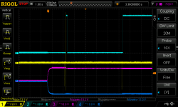
There seems to be a glitch on pin 18 during poweron that causes it to go high during one of the pulses emitted on the analog outputs. I used a 27k resistor, did not have 27k4 on hand.
Here are the signals during power on.
CH1 (yellow) is the unbuffered analog output.
CH2 (cyan) - pin 18
CH3 (magenta) - V+ on J1 connector
CH4 (blue) - V- on J1 connector
Notice how pin 18 goes high for a short while during power on. The last output pulse happens right before pin18 goes properly high. I would prefer to have a slightly longer poweron mute period, just in case the timing of that last pulse varies. Does it depend on the resistor value?
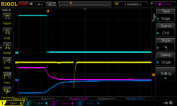
Zooming in we can see the pin18 glitch enables output right before a major pulse:
Power off looks good, pin 18 goes low before any disturbance on analog out.
Attachments

There seems to be a glitch on pin 18 during poweron that causes it to go high during one of the pulses emitted on the analog outputs. I used a 27k resistor, did not have 27k4 on hand.
Here are the signals during power on.
CH1 (yellow) is the unbuffered analog output.
CH2 (cyan) - pin 18
CH3 (magenta) - V+ on J1 connector
CH4 (blue) - V- on J1 connector
Notice how pin 18 goes high for a short while during power on. The last output pulse happens right before pin18 goes properly high. I would prefer to have a slightly longer poweron mute period, just in case the timing of that last pulse varies. Does it depend on the resistor value?
Zooming in we can see the pin18 glitch enables output right before a major pulse:
Power off looks good, pin 18 goes low before any disturbance on analog out.
You really check things 🙂
27K resistor is ok.
Looks fine on my scope, but checking the firmware I could imagine a situation, depending on how the dam1021 is powered, that could do that.
In you first scope screendump it seems like that the power off circuit is actually triggered just as the EN_AUD signal goes high as it power up again after five seconds.... Can you do the same plot, but with the -4V ref instead of the -12V input power ?
Will investigate and fix it.
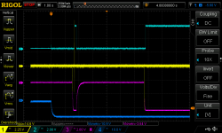
Here is a trace with Vref.
CH3 (magenta) is -4V ref
CH4 (blue) is -12V input power
This is with unmodified DAM hardware, only the 27k resistor is added.
Input power is +/-12V from simple LM317/337 regulators with 2x2200 uF filter caps per side.
Another strange thing is that the poweron output pulse amplitude is so high - well above 10Vpp, on one occasion I saw 20Vpp. How can those voltages appear on unbuffered output? Perhaps the output opamps are wreaking havoc?
Attachments
abra,
Where have you found smd tantalum resistors?
From what I have read the VISHAY as sold by MOUSER are considered good.
There is a fellow (carlsor) who has found the SUSUMI resistors to be superior but be careful since many of theirs have the contacts mounted on the long axis.
Where have you found smd tantalum resistors?
From what I have read the VISHAY as sold by MOUSER are considered good.
There is a fellow (carlsor) who has found the SUSUMI resistors to be superior but be careful since many of theirs have the contacts mounted on the long axis.
How difficult would it be to have the DAC measure nonlinearities due to resistor inaccuracies and then calibrate output to account for them?
Strange behaviour, this is the third day with the new firmware update, today after 2 hours playing music the dac volume start dancing... Via serial the terminal window showed randon values of volume, V+10, V+05, V+00.... stopped until recycling power! After an hour and a half the same problem! I am wondering if anyone else has had the same problem?
Ps : my setup>>> amanero, raw output to B1 salas and updated to last firmware plus the new filters EQHQ variations v1, vref mod copied from Hifiduino 4x470uf
Also after vref mod foobar and asio combo 384 is much beter than wasapi, My foobar setup: ??????? Foobar
Ps : my setup>>> amanero, raw output to B1 salas and updated to last firmware plus the new filters EQHQ variations v1, vref mod copied from Hifiduino 4x470uf
Also after vref mod foobar and asio combo 384 is much beter than wasapi, My foobar setup: ??????? Foobar
Last edited:
- Home
- Vendor's Bazaar
- Reference DAC Module - Discrete R-2R Sign Magnitude 24 bit 384 KHz