Please elaborate a little on what you mean here.
we cure the symptoms of a disease, but not resolving the real problem...
it would be much much easier if we had a real and full buffer circuit scheme, but....
By the way, this strange distortion of power supply has the maximum value on 12 kHz. The signal has less distortion level on other frequencies. And it doesn’t depend from a clock frequency: 48, 96, 192 and 384 has the same behavior. The main question is why?
Which digital filter did you use? If anything else then NOS then the situation at the shift registers is for all mentioned frequencies more or less equal, i.e. instead of interpolated values you only use more exact ones when going up with fs.
It could be interesting to repeat the measurement with the NOS filter (if not already done).
One question about skr file format. Would it be possible to get specification of that? I would like to implement generating filter files on-fly at some point.
we cure the symptoms of a disease, but not resolving the real problem...
it would be much much easier if we had a real and full buffer circuit scheme, but....
Thanks, I get it now.
In my set up the raw output is plenty to drive a multi amped system so I am hesitant to add another amplification stage unless there is a very good reason to do so.
Looking forward to reading what you come up with, next.
The extra caps, with some time on them, are allowing the sound to open up - "unsticking" from the speakers to paraphrase your apt description.
Thanks for your work!
First of all, … I want to declare my mistake. Wineds, you are right! Nevertheless to good practical results(thanks to cap), my proposition to using a transistor in that (mod #2) way was wrong (feedback, repeater….), because I overlooked the opamp marking … additional measurements....
But…
The researching is going…. Lots of interesting are coming soon including new transistor approach, new mods, new measurements, new discoveries and lots of photos🙂
But…
An externally hosted image should be here but it was not working when we last tested it.
The researching is going…. Lots of interesting are coming soon including new transistor approach, new mods, new measurements, new discoveries and lots of photos🙂
Last edited:
First of all, … I want to declare my mistake. Wineds, you are right! Nevertheless to good practical results(thanks to cap), my proposition to using a transistor in that (mod #2) way was wrong (feedback, repeater….), because I overlooked the opamp marking … additional measurements....
But…
An externally hosted image should be here but it was not working when we last tested it.
The researching is going…. Lots of interesting are coming soon including new transistor approach, new mods, new measurements, new discoveries and lots of photos🙂
Hey man your pictures are never high resolution nothing is clearly visible. Please upload new pics atleast as links.
Please post your transistor mod pic.
what voltage cap to be chosen for the 470uf can it be 6.3V?
If 6.3V is chosen then we can get as low as 7mohms and if 16V has 10mohms.
If 6.3V is chosen then we can get as low as 7mohms and if 16V has 10mohms.
I can confirm, by only adding a small cap 22uf smd tantalum (from an old graphic card, hard time here in Greece...) as Soren proposed trough the mod picture, with only this small added capacity, R2R is in a different league...!
Waiting for alecm interesting research...!
I use Paul's last filter + a placid HD shunt + DCB1 after R2R + amanero+foobar, no other mods on pcb except of this four small caps!
Waiting for alecm interesting research...!
I use Paul's last filter + a placid HD shunt + DCB1 after R2R + amanero+foobar, no other mods on pcb except of this four small caps!
Last edited:
what voltage cap to be chosen for the 470uf can it be 6.3V?
Yes, 6.3v caps are OK for the 4v references.
Yes, 6.3v caps are OK for the 4v references.
I'm using 6.3v OSCON's on the 5V regulators, likely pushing the limits of the cap however they are only slightly warm, sinking heat from the ground plane from the regulators most likely. The cap I have soldered to the 3.3V LDO outputs gets even warmer because of that. I'll be using these same caps on the 4V references as well. Very low ESR on the 680uF SP ver, something along the lines of 4mohms.
I can confirm, by only adding a small cap 22uf smd tantalum (from an old graphic card, hard time here in Greece...) as Soren proposed trough the mod picture, with only this small added capacity, R2R is in a different league...!
Waiting for alecm interesting research...!
I use Paul's last filter + a placid HD shunt + DCB1 after R2R + amanero+foobar, no other mods on pcb except of this four small caps!
so just with the 4 x 22uf smd mods have changed the sound substantially?
so just with the 4 x 22uf smd mods have changed the sound substantially?
Yep, exactly as described in #2981 alecm post!
So i soldered some conventional 220u electrolytes on the ceramics and ruined those and the ones next to those (shorted).
It was the first small smd i ever touched.
Is 250 deg really too much? I have a large flat tip, maybe it has too much heat capacity?
It was the first small smd i ever touched.
Is 250 deg really too much? I have a large flat tip, maybe it has too much heat capacity?
Last edited:
Can't imagine you getting your solder to melt at all at that temperature.
And the stuff they use for production is even harder to melt.
You will need a small tip.
How I did it:
First tin the ends of your caps and put a little of your solder on the ends of the SMD caps - you can tack one end on and then be able to make a real solder joint on the other end. Then go back and resolder the first side.
Don't be tempted to use too much solder. You will just have to go back and clean up the mess. In this case, better to heat a little too long than not long enough. You want that minimal amount of solder to spread evenly.
250 is way too low, for leaded soldering (the easy stuff) I use 320°C, for leadfree soldering (the terrible stuff) I use 350-360°C.Is 250 deg really too much?
This DAM board is probably leadfree.
Pretinning both the dam and new cap leads are a must. It makes it all the easier as things simply melt together when you mount the caps.
250C is way too low given the amount of ground planing in the board.
250C is way too low given the amount of ground planing in the board.
So i soldered some conventional 220u electrolytes on the ceramics and ruined those and the ones next to those (shorted).
It was the first small smd i ever touched.
Is 250 deg really too much? I have a large flat tip, maybe it has too much heat capacity?
Use lots of flux and desoldering braid to fix that. 280 degree would be fine. Suggested 350 might irreversibly damage smd components.
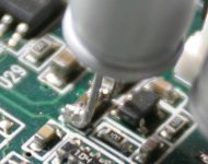
I selected caps with 3.5mm lead spacing, cut leads to comfortable length (could be shorter...)
Then made sure polarity orientation was correct and bent leads 90 degrees for 1 to 1.5mm such that they aim away from opamp.
Then narrowed them slightly so that the snugly fit over SMD cap and would free stand without my having to hold them.
Then I pre-tinned cap "feet" and put them back in position.
Heating one side while holding the cap down, allowing to cool completely before heating the other side.
Attachments
- Home
- Vendor's Bazaar
- Reference DAC Module - Discrete R-2R Sign Magnitude 24 bit 384 KHz