Yes, but observe proper polarity.May I ask the connection is correct or not?
Wow, thats really cool work Alecm! I have a question towards the 10 Ohm resistor which is making noise. Is it the current noise of this resistor that makes such distortion? If yes, I think we can just change it with low noise resistors, e.g. Vishay high precisions or simply some good wire wound resistors. The high inductance of wire wounds may also help to filter out the noise IMO.
Thanks!
The 10 Ohm resistor problem is widely described in the opamp datasheet.
http://www.ti.com/lit/ds/symlink/opa365.pdf, page 10, CAPACITIVE LOADS.
So this problem wouldn't be decided by using more quality resistor.
I made all important bypass yesterday. I used one Nichicon FP series 330µFx16V polymer (7mohm esr ballpark) for each suggested decouplig point, plus I decoupled the 78L05/79L05 (this is mod#2 less regulator change). In future I will substitute them for low noise shunt low Z shunt regulators. I not used the transistor buffer and *maybe* I don't need them now (I will check with an scope). I continue to use the EQHQ digital filter.
The sound now is very different to original sound. Now sounds really good. Before, my older DACs sounded a little better, but now the DAM is leading. And better here significates absence/low level of electronic colourations; more natural and open sound. Now is time to make an FFT reading and compare.
Alecm made an very good work here (and other with good ideas)!🙂
PS.: my older DACs include: EAD DSP-1000 series III with DIY analog section style Zen I/V (FAR better than original), DIY PCM1704 with à la Audio Note I/V conversion (nanocristallyne toroidal core trafo) plus Aikido E88CC Siemens for buffering and a Schiit DSD DAC.
The shunt regulator in DAM is an TL431 and I bypassed the output to ref pin, to reduce a little the TL431 own self-generated noise (this voltage reference is post-filtered in the DAM of course, but is better if source is clean, anyway...).
.... but the exact value will be random according to the actual vbe of the device used. Hence all the good work done by the circuity to this point to keep both +/- rails exactly the same will be undone and additional distortion will be end result. I agree with Soren that the main source of this temporary fix is the 220uf capacitor and not the transistor.
A transistor influence on the Vref is the subject of theoretical disputes! I prefer to check everything on practice. From practical point of view, the distortions are not changed significantly without capacitors. More truly, they are changed by the shape more than by the size. Sure, the biggest influence to noise reduction done by additional capacitors. I already supported Soren’s proposition to check the impact with capacitors only (without using transistors). Now I have no nearest plans to check it again due to the soldering complexity.
So I propose you to start implementing Soren’s proposition in practice and see the shapes of signal on register’s legs, for sure it has to be the 12 KHz (full scale) to the DAC input. And pls check the AC part of +/-4 V on the register's legs. And again, put 20 Hz to the input and check Vcc again. As well please public the pictures in both cases. 🙂
Last edited:
I made all important bypass yesterday
.....
The sound now is very different to original sound. Now sounds really good. Before, my older DACs sounded a little better, but now the DAM is leading. And better here significates absence/low level of electronic colourations; more natural and open sound.
Excellent! Thanks for sharing the results.
Re: shunt regulators
Wineds,
Well, that is settled now, isn't it? Now SOEKRIS can tell the world his DAC board has shunt regulation! Though some might find the assertion misleading nonetheless it would be true.
Wineds,
Well, that is settled now, isn't it? Now SOEKRIS can tell the world his DAC board has shunt regulation! Though some might find the assertion misleading nonetheless it would be true.
So after this mod, is there anymore to gain with bypassing the 78L05/79L05 pair and externally sourcing them with a pair of Salas shunts? (Other than keeping the clock source cooler as these regulators run warm)
Thanks!
The 10 Ohm resistor problem is widely described in the opamp datasheet.
http://www.ti.com/lit/ds/symlink/opa365.pdf, page 10, CAPACITIVE LOADS.
So this problem wouldn't be decided by using more quality resistor.
Alecm,
The compensation scheme for capacitive loads used by the DAM Vref buffer is not described in the OPA365 datasheet. Its uses in the loop compensation like this : http://www.analog.com/library/analogdialogue/archives/38-06/3806_03.gif (with resistor Rin being infinite in this case)
Last edited:
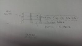
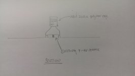
From Soren recommendation to use 47 uF x5R 6V3 0805, the connection will be like as shown picture??
Thanks so much
Exactly.
Interesting info over on our filter maestro Paul's website here :
vref Regulator Mods | moreDAMfilters
He links an article by BB which appears to describe the vref buffer configuration :
http://www.ti.com/lit/an/sbva002/sbva002.pdf
It seems to shed some light on the 12KHz sensitivity issue Alecm has observed. The article does state that for this kind of configuration that :
(CLOAD + C1) • R1 < 0.5 • R2 • C2
In this case if we are looking to increase C1 to ~500uF with R1 = 10 ohm, then C2 must be at least 20uF given R2 as 500 ohm. Looking at the PCB C2 doesn't look big enough to be 20uF at present.
Last edited:
Correct. And these caps don't have polarity to worry 😉.From Soren recommendation to use 47 uF x5R 6V3 0805, the connection will be like as shown picture??
Thanks so much
PS.: I only saw the Soekris response after publishing my post... I need to press F5 more times...
Last edited:
Increasing cap capacity didn’t affect significantly to Vref frequency with maximum distortions. 12 KHz still is 12 KHz, even after adding 220uf.
Seems that digging process going in wrong direction…
Seems that digging process going in wrong direction…
Thanks wineds for the notice about spzzzzkt's new site.
A new reference for the SOEKRIS enthusiast!
A new reference for the SOEKRIS enthusiast!
Increasing cap capacity didn’t affect significantly to Vref frequency with maximum distortions. 12 KHz still is 12 KHz, even after adding 220uf.
Seems that digging process going in wrong direction…
Please elaborate a little on what you mean here.
I placed 1000uF/16v OSCONs last night - all I had on hand. Seemed to make more of a difference in dynamics than anything else. Not that I am complaining! Maybe this is too much capacitance?
I did detect it getting better with time so maybe those caps need to settle in. I leave the SOEKRIS on all of the time so looking forward to hearing what it sounds like tonight.
Take care,
Hmmm ... I was thinking just now about the following: the opamp will filter the output with reference to his own positive (non-inverting) input. So if we measure this point with respect to a distant ground somewhere in the board, we will measure unwanted signals from another place (even high-quality ground planes will be some residual at extremes places). To find out if the output of the opamp is clean, we must measure connecting the oscilloscope earth (or the negative of balanced input) right next to the opamp filter ground (probably in the output filter cap). I'll try to make this measurement when I have time to play again with the DAM.Increasing cap capacity didn’t affect significantly to Vref frequency with maximum distortions. 12 KHz still is 12 KHz, even after adding 220uf.
Seems that digging process going in wrong direction…
Of course, forgive me if you guys have already taken this caution, but is worth remembering.
... we must measure connecting the oscilloscope earth (or the negative of balanced input) right next to the opamp filter ground (probably in the output filter cap).
i did it exactly in this way...
- Home
- Vendor's Bazaar
- Reference DAC Module - Discrete R-2R Sign Magnitude 24 bit 384 KHz