I also like the sound of a single ended tube/valve amp. However, I also know it is generating lots of harmonics and other artefacts that are naturally appealing to my ear and brain but not an accurate reproduction of the recording. There is nothing wrong with liking an inaccurate but subjectively appealing reproduction chain, their is everything wrong in claiming it is objectively better.agreed but it does have to be the final judge. I am my sure my old solid state power amp measures significntly better in all areas, but it does not sound better.
It is often quoted that the power supply is one of the most important elements within any design, and it's relatively common to buy better power supplies within a range of products purely to improve the sound quality (Naim audio being a classic example) so in effect you always hear it.
agreed, what I am after is some knowledge of the science to explain what may be voodoo or personal subjective opinion.
I was helpfully advised to look at PSUD2 as a tool to apply physics to model any system changes, and what I am after is some guidance on what the simulations should be designed to achieve, beyond the correct voltage and low ripple.
Thanks for the link, I will have a read up on this 🙂
PSUD2 is a fun tool - it pays to do a lot of concurrent reading because, like any tool, its the considered interpretation of the measurements that makes it useful, not the numbers themselves. I've always found it to be a pretty good predictor of real world performance, but you should try out any model you settle on not just expect it to translate literally from the computer screen to your breadboard! I've never been up in the voltages you are modelling, so ymmv.
Have fun!
ok - this is super interesting, and EXACTLY the guidance/insight and I was hoping for thanks so much!A psu primary function is ripple filtering but this is not the whole story. Its output impedance across audio band is also important. Too high and B+ will sag at transients, too low and it will ring. There is a way to look for this in PSUD2 and this is the start up slope if regarded as a load variation. Or use a stepped load.
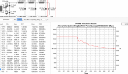
So here are 2 plots and you can see the difference in the transient response for a step change in current draw after 6 seconds this compares the CLCLCLC to CLC what I have not put in accurately is the resistance of the caps due to lack of info but I feel like this tells an interesting transient story....this does look like a ringing/oscillating response from the CLCLCLC compared to the CLC, it also takes longer to return to a stable supply.
Attachments

agreed but it does depend of course on your objective, mine is listening to a system that represents as near a live performance in full dynamic colour as I can, and for my ears, low power SET and horn speakers make more musical realism and enjoyment than large solid state amps with medium or low efficiency speakers, I have owned both 🙂I also like the sound of a single ended tube/valve amp. However, I also know it is generating lots of harmonics and other artefacts that are naturally appealing to my ear and brain but not an accurate reproduction of the recording. There is nothing wrong with liking an inaccurate but subjectively appealing reproduction chain, their is everything wrong in claiming it is objectively better.
Thanks, and see later post from MagicBus which is super interesting, and insightful.PSUD2 is a fun tool - it pays to do a lot of concurrent reading because, like any tool, its the considered interpretation of the measurements that makes it useful, not the numbers themselves. I've always found it to be a pretty good predictor of real world performance, but you should try out any model you settle on not just expect it to translate literally from the computer screen to your breadboard! I've never been up in the voltages you are modelling, so ymmv.
Have fun!
Now whilst I may appear an ears before science kind of guy and voodoo trumps proof I should counter this by explaining that I am an Engineer, and I used be a senior lecturer at a University, and have patents to my name and have created lots of interesting tests to objectively prove things (e.g. heat pipes oscillation in the satellite launch phase for Marconi).
BUT I also studied at the Royal College of Art, and believe there is a mix of art(subjective) and science(objective) 😎
and yes I am having fun!!

Psu design is like speakers, where you can't have low bass, high efficiency and small size all together. My example is used in a push pull amp with CCS so load is stable and I could choose for a higher impedance for shake of better filtering. A SE amp may need the opposite approach. You will want to find the best compromise for your case. Your CLCLCLC has lower impedance than the CLC thus less "damping" if we may use this term. You could play around components values -capacitors' is more practical and/or insert small in series resistors to the inductors- to achieve a similar performance from both.ok - this is super interesting, and EXACTLY the guidance/insight and I was hoping for thanks so much!
So here are 2 plots and you can see the difference in the transient response for a step change in current draw after 6 seconds this compares the CLCLCLC to CLC what I have not put in accurately is the resistance of the caps due to lack of info but I feel like this tells an interesting transient story....this does look like a ringing/oscillating response from the CLCLCLC compared to the CLC, it also takes longer to return to a stable supply.
PS: I'm not an EE. I have played a lot with PSUD2 and it is very helpful.
A little maths please. The cutoff frequencies of both your suggestions are five octaves or more below 120 Hz. So your choice is between a two-pole filter with 5x2x6=60 dB of attenuation at 120 Hz, or a six-pole filter with 5x6x6=180 dB of attenuation at 120 Hz. 180 dB is certainly far more than necessary, but in SE Class A 60 dB is certainly not enough, as an SE output stage has no PSRR whatsoever.
Compared to this, the dubious ringing that is claimed without proof to be the same as the startup condition is not significant.
Compared to this, the dubious ringing that is claimed without proof to be the same as the startup condition is not significant.
The oscillations here are based upon the step change in the constant current simulation at 6sA little maths please. The cutoff frequencies of both your suggestions are five octaves or more below 120 Hz. So your choice is between a two-pole filter with 5x2x6=60 dB of attenuation at 120 Hz, or a six-pole filter with 5x6x6=180 dB of attenuation at 120 Hz. 180 dB is certainly far more than necessary, but in SE Class A 60 dB is certainly not enough, as an SE output stage has no PSRR whatsoever.
Compared to this, the dubious ringing that is claimed without proof to be the same as the startup condition is not significant.
Thanks for this, and to better understand your logic of not enough attenuation so looking at the simulation the resultant ripple is 58mV. Which is as you say ~60 dB below the simulated output after the rectifiers at ~60V.
Now the output to the speakers will be less through the transformer, I was explained that 40mV of B+ would probably reduce to less than 1mV at the speakers and that even 100mV at the output of B+ would probably be fine?
The simulation does not match what actually happens. After 6s the voltage in the real amplifer is still zero base the rectifiers haven't warmed up, and they give a much slower and steadier rise than the simulation shows. The assertion that this has anything to do with steady state behaviour remains unsubstantiated.
ok - thanks so I should not trust the simulation during start up or current load changes?The simulation does not match what actually happens. After 6s the voltage in the real amplifer is still zero base the rectifiers haven't warmed up, and they give a much slower and steadier rise than the simulation shows. The assertion that this has anything to do with steady state behaviour remains unsubstantiated.
are you able to answer the other question / offer advice on the level of ripple that is likely to be acceptable?
Psu design is like speakers, where you can't have low bass, high efficiency and small size all together. My example is used in a push pull amp with CCS so load is stable and I could choose for a higher impedance for shake of better filtering. A SE amp may need the opposite approach. You will want to find the best compromise for your case. Your CLCLCLC has lower impedance than the CLC thus less "damping" if we may use this term. You could play around components values -capacitors' is more practical
To model additional resistors in series with inductors do you just add these to the inductor resistance as if the inductor had a higher value in the simulation? then in real life of course connect in series?and/or insert small in series resistors to the inductors- to achieve a similar performance from both.
In practice I guess apart from lowering the voltage into the inductors if before the additional resistors could be before or after the inductor, as long as they were after the cap to ground?
PS: I'm not an EE. I have played a lot with PSUD2 and it is very helpful.
The point is that you can't use a simulated startup which doesn't actually happen as evidence of what might happen later. This is modelling gone crazy. You call it open-minded: I call it credulous.ok - thanks so I should not trust the simulation during start up or current load changes?
are you able to answer the other question / offer advice on the level of ripple that is likely to be acceptable?
Not knowing the gain or power or OPT turns ratio or anything else about your amplifier, or your intended speaker, it is impossible to comment on acceptable ripple level in any way.
I've been reading Merlin Blencowe's "Designing Power Supplies for Tube Preamps" in which he discusses the unwanted resonances you'll encounter using LC filters, due to the inductor's changing impedance with frequency. A single choke with a single cap will have a resonance. It follows that a cascade of Ls and Cs will have multiple resonances. A simplified description of an LC smoothing filter's behavior is available on Merlin's Valve Wizard site: https://www.valvewizard.co.uk/smoothing.html
It also changes its inductance with current, which is yet another reason why the alleged startup behaviour may not match real performance.
For the inexperienced the PSUD2 software appears to be a pathway to predict PS performance, and the resonance frequency formulae for an LC filter is I would expect embedded in the maths of the simulation?The point is that you can't use a simulated startup which doesn't actually happen as evidence of what might happen later. This is modelling gone crazy. You call it open-minded: I call it credulous.
I guess you don't have any faith in the package, but for someone without experience it seems an option to learn from, and its reputation in the DIY community seems to suggest that it does offer value.
ok noted on acceptable ripple in detail, however you did comment on this " but in SE Class A 60 dB is certainly not enough, as an SE output stage has no PSRR whatsoever." so I had assumed this was based on some primary logic?Not knowing the gain or power or OPT turns ratio or anything else about your amplifier, or your intended speaker, it is impossible to comment on acceptable ripple level in any way.
This was the detail used in the assertion that 40mV was enough from another contacts primary logic btw:
Your output tube has (internal) resistance (say 4K) and your output transformer has 10K impedance.
These 2 parts act as a “volume control” for the power supply humm. A part of this humm is distributed to the output transformer. About 10K / (10 +4)K * 40mV = 29mV is distributed to the output transformer.
You output transformer is a 10K to 8R transformer. Turn ratio is the square root of 10000/8 = 35. So an input voltage of 1Vrms at the primary side is 35 times attenuated at the secondary side. 29mV / 35 is 0,82mVrms power supply humm at the 8R tap.
Then I would think even 100mV humm should be no problem.
It's hard to develop understanding with so much contrary opinion on things hence my persistent questions, so just to say that I really do appreciate everyone having the patience and energy to bother answering in the first place!
Thanks
100mV hum is about -22dBW. For two speakers nearfield of 88dBSPL/1W/1M summed non-coherently (most conservative [random] case) that's a hum level of 91dBSPL -22db equals 69dBSPL at 1M, a fairly loud sound.
If your goal is to justify somebody else's "unique" theory, you should probably begin with a stronger case. The subject involves more than just noise and the dynamic response of the complete power supply to signal demands, but those have to be addressed first, and not trivially. But when that somebody else claims any magical improvements over established practice, you should expect a hard eyed look at those claims. Of course.
All good fortune,
Chris
Correct!To model additional resistors in series with inductors do you just add these to the inductor resistance as if the inductor had a higher value in the simulation? then in real life of course connect in series?
In practice I guess apart from lowering the voltage into the inductors if before the additional resistors could be before or after the inductor, as long as they were after the cap to ground?
Similarly, it still surprises me that people think stuff can be heard that cannot be measured. I differentiate between "able to be measured" and "knowing what and how to measure".
However, this is not a subjective/objective argument. In a power supply it is very easy to measure key parameters that influence the sound output. Voltage sag and ripple (including any harmonics) are trivial to measure and the audible fingerprint of them is clear.
So your the one person who can then. I’m sure if that were the case you could save a lot of manufacturers a lot of money
This calculation I think assumes 100mV is across the speaker and the calculation offered (not by me) was that this is at the output of the B+ and when this is ultimately seen across the speaker it is significantly reduced.100mV hum is about -22dBW. For two speakers nearfield of 88dBSPL/1W/1M summed non-coherently (most conservative [random] case) that's a hum level of 91dBSPL -22db equals 69dBSPL at 1M, a fairly loud sound.
Interestingly I also did a quick simulation of Thomas Meyers 211 design in this article and saw the ripple of B+ in his final design with the additional electrolytic caps in the simulation come out at 84mV (and here at 1145v) his original design without the additional caps came out at 1.4V!
The reason for quoting the article was not to support it or otherwise see it as a magic piece of fresh insight. I found it as the only tutorial style example as the use of PSUD2 and saw here the apparent importance of other factors beyond ripple and correct voltage. This was what my original question/post was framed around.If your goal is to justify somebody else's "unique" theory, you should probably begin with a stronger case. The subject involves more than just noise and the dynamic response of the complete power supply to signal demands, but those have to be addressed first, and not trivially. But when that somebody else claims any magical improvements over established practice, you should expect a hard eyed look at those claims. Of course.
If it is tosh and nonsense then that's fine by me but it still begs the question what else can you look at using PSUD2 as a tool to explore power supply design beyond voltage output and ripple. Any other guidance/articles/knowledge gratefully received.
Thanks for the reply.All good fortune,
Chris
🙄So your the one person who can then. I’m sure if that were the case you could save a lot of manufacturers a lot of money
This calculation I think assumes 100mV is across the speaker and the calculation offered (not by me) was that this is at the output of the B+ and when this is ultimately seen across the speaker it is significantly reduced.
Interestingly I also did a quick simulation of a 211 design in this article and saw the ripple of B+ in his final design with the additional electrolytic caps in the simulation come out at 84mV (and here at 1145v) his original design without the additional caps came out at 1.4V!
The reason for quoting the article was not to support it or otherwise see it as a magic piece of fresh insight. I found it as the only tutorial style example as the use of PSUD2 and saw here the apparent importance of other factors beyond ripple and correct voltage. This was what my original question/post was framed around.
If it is tosh and nonsense then that's fine by me but it still begs the question what else can you look at using PSUD2 as a tool to explore power supply design beyond voltage output and ripple. Any other guidance/articles/knowledge gratefully received.
Thanks for the reply.
sorry amended this - no idea why I linked the article to the wrong person the 211 article is by Nick Soudas....ooops
Reason that CLC version ‘sounds better’ could be because transient response is much better with three capacitor cells in parallel, providing lower output impedance across the frequency range.
My view on power supply for audio is:

CRC under 1 A DC + 1 kHz 1.75 A rms load. PS under AC load produces harmonics. H2 harmonic is 30 dB below rail modulation caused by load from the amplifier and H3 is another 10 dB lower.

Someone should compare rails of CLCLCLC vs. CLC under load, for harmonics and transient response.
Example of clean transient response of regulated PS under hard conditions. There should be small voltage variation and no ringing:

My view on power supply for audio is:
- Amplifier is an extension of its power supply. There can’t be an excellent amplifier with bad power supply.
- Ripple level is important (overrated) . Transient response is neglected, but even more important.
- Power supply, even simplest CRC or CLC, is a nonlinear circuit that produces distortion (harmonics).
- Operation of power supply is indeed ruled by physics laws, but different components with their properties like ESR, ESL, dielectric absorption, inductance over frequency and current, hysteresis, parasitic capacitance and so on, will introduce some ‘voodoo’ factor, as PS circuit linearity and transient response will change.
- Different power supplies can, by small measure, change sound of an amplifier, especially one with low or nonexistent PSRR.
CRC under 1 A DC + 1 kHz 1.75 A rms load. PS under AC load produces harmonics. H2 harmonic is 30 dB below rail modulation caused by load from the amplifier and H3 is another 10 dB lower.
Someone should compare rails of CLCLCLC vs. CLC under load, for harmonics and transient response.
Example of clean transient response of regulated PS under hard conditions. There should be small voltage variation and no ringing:
- Home
- Amplifiers
- Tubes / Valves
- Reconfiguring an existing Power Supply using PSUD2 - could use some second opinions :-)