Take a look at how a common cathode amplifier works.
That 22k resistor is the load on the plate of the 5842.
Is you remove that 22k resistor, the 5842 won't have a load it can work into, and it won't make any voltage amplification.
That 22k ohm resistor does far more than just burn off voltage.
Here's an article about this subject:
http://www.valvewizard.co.uk/gainstage.html
🤦♂️ thanks both, I realize now how basic this is.One tube can not work alone. We usually have a tube -and- a resistor in a "fight", pulling up -and- down.
Most MM carts output 3-5mV, so even with 10mV input to the first stage, with ~40X gain would need to swing less than a volt.
The second stage roughly 15-20V ... so isn't 220V between the plate and B+ excessive?
Or actually, this seems to be the wrong direction to think about this ... I assume the designer preferred a 22K plate resistor as a "good" load for the 5842, and with Vp=100V the B+ had to be 320V.
A choke load or a CCS would allow running at much lower B+, correct?
Separately, regarding the Steve Bench RIAA 5 schematic (which @6l6pp recommended), isn't the output coupling cap too small at 0.15uF?
With a 25K load (and today even 10K is common), that would result in -3dB frequency of 40Hz.
The last stage only makes enough for the Line Input of the system, a volt or so. MAYBE 10V in an extreme case, but rare.The second stage roughly 15-20V ... so isn't 220V between the plate and B+ excessive?
THD will drop as supply voltage is raised. At MAXimum (unclipped) level the THD is about 5%. To get 0.5% we have to work nearer 1/10th of maximum level (or sock it with NFB which has other issues). At 320V supply we might get 90Vrms at clipping and 5% THD just below that, so 0.9Vrms implies 0.05%THD, OK for most uses.
In a TUBE system, 100k is low and 25k is absurd. Dynaco went to some trouble to drive 47k out of the PAS preamp.I assume the designer preferred a 22K plate resistor as a "good" load for the 5842, .....
.....isn't the output coupling cap too small at 0.15uF? With a 25K load (and today even 10K is common), that would result in -3dB frequency of 40Hz.
Usually a triode should be loaded in at least 2X, better 5X, its plate resistor, so 22K plate resistor suggests 44k better 110k loading. A 0.15uFd value may also be the biggest 400V 'film' cap that fit the box or the budget.

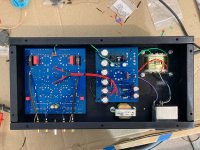
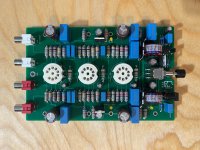
Finally finished the PH-16 build. I only bought the PCBs from VTA/Roy since I preferred a different look than the kits.
I wasn't entirely happy with some aspects of the build (at least compared to other PCBs/kits I've built previously), but must admit it sounds VERY good in my system.
I wasn't entirely happy with some aspects of the build (at least compared to other PCBs/kits I've built previously), but must admit it sounds VERY good in my system.
Attachments

I've been listening to the PH-16 for the past 2 months and it really is a great phono. With good 6922 tubes it is extremely quiet.
Can the 0.15uF output capacitor be increased to something like 0.47-1uF for less low-frequency roll-off with 50K load or can it cause undesired side-effects?

Starting to work on the Steve Bench RIAA 5, I've got the parts and almost finished designing the PCB.Usually a triode should be loaded in at least 2X, better 5X, its plate resistor, so 22K plate resistor suggests 44k better 110k loading. A 0.15uFd value may also be the biggest 400V 'film' cap that fit the box or the budget.
Can the 0.15uF output capacitor be increased to something like 0.47-1uF for less low-frequency roll-off with 50K load or can it cause undesired side-effects?
Save yourself the agony of putting the filament traces on the PCB copper. These are high current pathways.
2-layer? Put the two filament traces on opposite sides of the board on-top of each other to reduce hum leakage, use wider traces for filament. I see no attention to star-grounding layout either - this can matter with low-level signals. You are not using the full benefit of a 2 sided PCB - the ground network could be one side and signal/power the other.Here is the first iteration of the PCB... any feedback welcome
View attachment 1163581
The alternative is to solder the heater wires in the middle of the board which (IMO) makes the wiring messy. This is going to be 0.6A part of the way and then 0.3A, the Tubelab PCB's have much higher currents and seem to be working OK. It's a tradeoff I'm willing to make so that the heater wiring can go neatly at the bottom of the chassis.Save yourself the agony of putting the filament traces on the PCB copper. These are high current pathways.
@Mark Tillotson I've done as you've suggested with the heater wiring, which helps reduce the width of the board a bit. I'm not extremely concerned with hum from this because they will be DC anyway.2-layer? Put the two filament traces on opposite sides of the board on-top of each other to reduce hum leakage, use wider traces for filament. I see no attention to star-grounding layout either - this can matter with low-level signals. You are not using the full benefit of a 2 sided PCB - the ground network could be one side and signal/power the other.
Here is the updated board layout, which I think is a bit more organized.
Any other suggestions for the grounding scheme?

Hey all, I've assembled one board and need some help debugging THD / noise.
The PSU is a 220uF cap with tomchr maida regulator at 210V (B+ is around 300V so there is alot of headroom for regulation)
Heaters are regulated DC
The attached FFT's represent the following progression:
1) Initially, with the input shorted there was significant output (so seemed like an oscillation?). Attaching one leg of the DC heater to GND resolved that. (SB_PCB_PROTO.png)
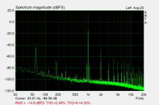
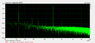
2) Now input is 10mV 1kHz, there is a significant 120Hz component. Connecting signal GND to the earth terminal in the PEM resolved it (perhaps it was a ground loop with the laptop/DAC?) (SB_PSU.png)
3) No more 120Hz, but 60Hz component is still very high and THD is higher than it should be. Based on the design, THD should be around 0.1% for 10mV input. (SB_PSU_EARTH.png)
Other info:
Any tips on what to look at next?
The PSU is a 220uF cap with tomchr maida regulator at 210V (B+ is around 300V so there is alot of headroom for regulation)
Heaters are regulated DC
The attached FFT's represent the following progression:
1) Initially, with the input shorted there was significant output (so seemed like an oscillation?). Attaching one leg of the DC heater to GND resolved that. (SB_PCB_PROTO.png)
2) Now input is 10mV 1kHz, there is a significant 120Hz component. Connecting signal GND to the earth terminal in the PEM resolved it (perhaps it was a ground loop with the laptop/DAC?) (SB_PSU.png)
3) No more 120Hz, but 60Hz component is still very high and THD is higher than it should be. Based on the design, THD should be around 0.1% for 10mV input. (SB_PSU_EARTH.png)
Other info:
- Voltages mostly align with the schematic, but I need to do a more detailed review to ensure nothing is off
- Output with 10mV (1kHz) input is 620mV output, which is about 36dB and close to the 38dB spec
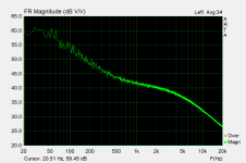
- Frequency response looks reasonable but I'll do a more detailed review once the THD/ noise issues are resolved.
Any tips on what to look at next?
Attachments

Some progress, I realized that the LA Autoranger has a 20k input impedance and that is likely too low for the 20K plate resistor, hence the high distorion.
I connected it directly to the Motu M4 and THD is down to 0.1% but noise is still high with the 60hz hump.
One other oddity here is with 10mV in --
1) open output -- ~900mV (39dB gain, per spec)
2) connected to autoranger (20k) -- 614mV (36dB)
3) connected to Motu M4 (input impedance not published) -- 314mV (only 30dB gain).
Nice boards mate....progress is good.
Here is a quote for you
"Wires are typically used to transmit signal using electrical current. By default, the flow of current generates an electromagnetic field of interference around the wire that creates noise the can impact signals being transmitted through surrounding wire and cable. In order to help eliminate this electromagnetic interference, the wire is twisted together to create a canceling effect. By twisting wires that carry an equal and opposite amount of current through them, the interference/noise produced by one wire is effectively canceled by the interference/noise produced by the other. A twisted pair also improves rejection of external electromagnetic interference from other equipment."
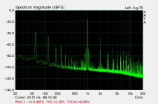
Thanks... I tidied up the wiring and also tried a different heater PSU and B+ PSU and 60Hz bump is there.
So I either I'm not wiring something correctly or its a defect in the board... wondering how I could rule one or the other out.
This is the FFT when connected to the Motu M4 directly
So I either I'm not wiring something correctly or its a defect in the board... wondering how I could rule one or the other out.
This is the FFT when connected to the Motu M4 directly
Attachments
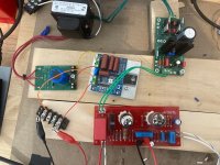
Morning...
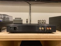
From the photos I don't see a mains earth connection....You have no doubt,but how have you wired it?
Looking at the circuit I see this is a split passive riaa implementation..A cascode into common cathode amplifier.But it does not have decoupling between these two stages
A cascode circuit is fundamentally a pentode....So very sensitve to its power supply ...basically it has very poor PSRR.
You have plenty of headroom to add further filtering ahead of the Maida Regulator.Either an RC or LC.I prefer LC but RC is cheaper.
With Phono Preamps distance is your friend,cascodes in particular ....You can do this by incrementally distancing your mains transformer from the riaa board.You'll find an optimum distance and orientation as you progress.
You are correct, initially there was no mains earth connection. I later made a connection which reduced the 120hz spikes.
The maida reg is supposed to have very low ripple (<20 uV) and works best without anything after it (maybe just a small cap next to the circuit).
I've also tried a CLC with 220uF-15H-220uF (which should be more than enough for the small mA) and the 60Hz spike remains the same.
I've also moved the power transformer and rotated but no difference, so at this point I may suspect improper ground on the PCB.
One bit of info, not sure if useful or not is if I remove the 2nd tube (the 6DJ8) the 60Hz drops down....
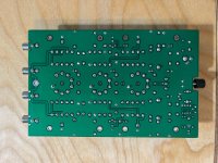
This was the final version of the PCB:

The maida reg is supposed to have very low ripple (<20 uV) and works best without anything after it (maybe just a small cap next to the circuit).
I've also tried a CLC with 220uF-15H-220uF (which should be more than enough for the small mA) and the 60Hz spike remains the same.
I've also moved the power transformer and rotated but no difference, so at this point I may suspect improper ground on the PCB.
One bit of info, not sure if useful or not is if I remove the 2nd tube (the 6DJ8) the 60Hz drops down....
This was the final version of the PCB:
"I've also tried a CLC with 220uF-15H-220uF"
Yes this is what I meant to say.... 🙂
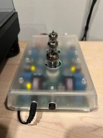
Would you take and show a picture of the set up right now,detailing the ground runs to mains earth.
Yes this is what I meant to say.... 🙂
Would you take and show a picture of the set up right now,detailing the ground runs to mains earth.
You have ground loop.
Several solutions are proposed online but a simple 2 diode ,resistor and capacitor set up will do.
valvewizard.co.uk/Grounding.pdf
Several solutions are proposed online but a simple 2 diode ,resistor and capacitor set up will do.
valvewizard.co.uk/Grounding.pdf
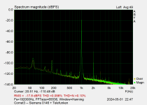
After the PH-16, I haven't gone back to debug the Steve Bench project, but I did buy the Hagerman Cornet3 PCB + chassis and I can highly recommend it to anyone.
The PCB layout is great, overall cost is low, it uses an external power supply, and it measures pretty good.
0.1% THD (2nd harmonic mainly) with wide and flat FR, see attached.
The PCB layout is great, overall cost is low, it uses an external power supply, and it measures pretty good.
0.1% THD (2nd harmonic mainly) with wide and flat FR, see attached.
Attachments

I agree, for me anyway. I used to use all tube systems, but have gone the way of the Jfet and Pass designs of late. Sometimes solid state amps don't act stable with tubes driving them,Hi, The easiest place to add tubes & get a MASSIVE upgrade is to add a Pass B1/Korg.
Tubes in phono stages are a hum nightmare if you do not get it exactly right. My SS phone system though the Pass is as quite in idle s my CD system.
Cheers
Not always.
I always added tube flavor at the power amp side. I hate ANY hum with phono. Right now use Pass diy Pearl 2, Pass diy Pearl 3 and Salas phono pre. All silent.
Russellc
- Home
- Source & Line
- Analogue Source
- Recommended phono preamp kit