The problem is, if you drive the grid the anode is in opposite phase, but if you drive the cathode the anode has the same phase.And since the feedback from the cathodyne goes to the cathode ...
Mona
Mona
I'm not sure if you reacted on my post. If so, which of my steps than do you think is/are wrong?
For me, the phase doesn't really matter. I just look at how the currents and voltages change and what effect they have on the input signal.
As to actually building it. I made two of these OTL amplifiers for 800 Ohm speakers in which this combination of positive and (more!) negative feedback is applied.
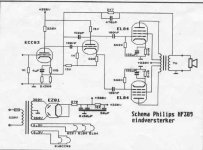
Philips applied this kind of power stages in different types of radios and in a line of Hi-Fi OTL amplifiers for 800 Ohm speakers. As far as I know Philips only applied this in a 'normal' amplifier (so with an output transformer) in their HF309.
For me, the phase doesn't really matter. I just look at how the currents and voltages change and what effect they have on the input signal.
As to actually building it. I made two of these OTL amplifiers for 800 Ohm speakers in which this combination of positive and (more!) negative feedback is applied.
Philips applied this kind of power stages in different types of radios and in a line of Hi-Fi OTL amplifiers for 800 Ohm speakers. As far as I know Philips only applied this in a 'normal' amplifier (so with an output transformer) in their HF309.
Attachments

A second attempt because my first attempt has flaws. The underlined parts are different from my post #40.
The output voltage of the first triode depends on voltage difference between its grid and its cathode. On a positive going input signal the voltage between grid and cathode becomes smaller. The negative feedback over the non-decoupled cathode resistor reduces this a bit because the rising current highers the cathode voltage a bit. This feedback is negative because a bit higher cathode voltage means a bit higher voltage difference between grid and cathode. But still the voltage between grid and cathode becomes smaller on a positive going input signal, else there would be no amplification at all.
The voltage on the anode of the first triode goes down, so also the voltage and current over and through the cathode resistor of the second triode goes down. This diminishing current of the second triode flows through the cathode resistor of the first stage. This lowers the voltage drop over the cathode resistor of the first triode. So it lowers the cathode voltage of the first triode. This in turn means that the voltage difference between the grid and the cathode of the first triode goes down. This falling difference has the same direction as the positive going input signal. So they add up.
Note that this is positive feedback (ofcourse) works in the opposite direction of that of the negative feedback caused by the first triode in its cathode resistor. But even if the amount of positive feedback is low, like even lower than the amount of negative feedback, still it is positive feedback.
As far as I can see, Mona explained it well in post #30. I just rewrite it in my own words here.
The output voltage of the first triode depends on voltage difference between its grid and its cathode. On a positive going input signal the voltage between grid and cathode becomes larger. The negative feedback over the non-decoupled cathode resistor reduces this a bit because the rising current highers the cathode voltage a bit. This feedback is negative because a bit higher cathode voltage means a bit lower voltage difference between grid and cathode. But still the voltage between grid and cathode becomes larger on a positive going input signal, else there would be no amplification at all.
The voltage on the anode of the first triode goes down, so also the voltage and current over and through the cathode resistor of the second triode goes down. This diminishing current of the second triode flows through the cathode resistor of the first stage. This lowers the voltage drop over the cathode resistor of the first triode. So it lowers the cathode voltage of the first triode. This in turn means that the voltage difference between the grid and the cathode of the first triode goes up. This rising difference has the same direction as the positive going input signal. So they add up.
Note that this is positive feedback (ofcourse) works in the opposite direction of that of the negative feedback caused by the first triode in its cathode resistor. But even if the amount of positive feedback is low, like even lower than the amount of negative feedback, still it is positive feedback.
OMG now there is negative and positive feedback in the same time ?
I'm afraid this are just fantasies ...
Examples on how other circuit works doesn't prove anything either
And driving the cathode doesn't make the anode signal be in phase

Last edited:
And driving the cathode doesn't make the anode signal be in phase
Of the 3 configurations: common cathode, cathode follower, and grounded grid only common cathode inverts the signal voltage.
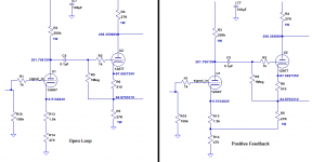
I found a little time to do some LTspice simulatin'. Let's settle this positive vs negative debate for good, with the help of some good ol' computering.
I took a basic cathodyne-based circuit like the one in question. It runs open loop with the output tubes in 'ultralinear' configuration. It uses a 12AX7 input stage with a 2k ohm Rk, RC-coupled to a 12AT7 cathodyne, which drives a push-pull pair of 6L6GC wired UL. The total gain of the amp turned out to be 15X (0.1V peak in, 1.5V peak out).
I then took the 2k Rk of the input 12AX7 and split it into a 1.5k and a 470R. Put those two resistors in series as the cathode load on that first stage, 1.5k from the 12AX7 cathode, 470R from there to ground. That's within 1.5% of the same value as the original 2k, so the gain remains unchanged.
Now for the test...
I took the 'bottom' of the cathodyne's Rk, disconnected it from ground, and connected it to the junction of the 1.5k and 470R resistors, with 470R to ground.
With the cathodyne lifted on top of the 470R resistor, the gain went *up* to 40X.
That's 2.67X (8.5dB) of *positive* feedback.
OK, now the question is... Why?
--
PS - The positive feedback makes the THD 6X worse adjusted for the same output voltage (closed loop with Vin/2.67).
Attachments
Last edited:
I found a little time to do some LTspice simulatin'. Let's settle this positive vs negative debate for good, with the help of some good ol' computering.
Now, can ya do up MY amp design and spill the details too?
Might be tricky with that Gillespie regulation system.
I do know it pumps out a beautiful sine wave under testing.
As Mona said, of course it's positive feedback - it's an simple matter of polarity, and no handwaving about "phase" can change that. This was done at least by the 1960s, in for instance, the Dynaco ST35.
And really, why would anybody want to incorporate negative feedback into the comparatively linear driver stages? It's daft. You'd want the extra driver stage gain to increase the amount of negative feedback around the long loop including the output stage, where it matters.
All good fortune,
Chris
And really, why would anybody want to incorporate negative feedback into the comparatively linear driver stages? It's daft. You'd want the extra driver stage gain to increase the amount of negative feedback around the long loop including the output stage, where it matters.
All good fortune,
Chris
And driving the cathode doesn't make the anode signal be in phase
Actually, yes, it does.
All good fortune,
Chris

OMG now there is negative and positive feedback in the same time ?
I'm afraid this are just fantasies ...
So if my revised explanation in post #43 'are just fantasies', and you know all about this type of feedback so well, surely you must be able to point out exactly which part or parts of my explanation in post #43 is/are wrong.
I eagerly await your response, especially now rongon showed that positive feedback is indeed going on.
It's time to put your money where your mouth is.
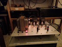
A vote for the Tubelab SPP, pretty much as simple as it gets.
As I used recovered iron, the rectifier is off-board and power supply is choke input.
Wasn't happy with UL, so it has stabilised (MOSFET and zener string) screen supply.
Plays nicely on a pair of Heresy Mk1. Some other tweaks, but that's another thread.
As I used recovered iron, the rectifier is off-board and power supply is choke input.
Wasn't happy with UL, so it has stabilised (MOSFET and zener string) screen supply.
Plays nicely on a pair of Heresy Mk1. Some other tweaks, but that's another thread.
Attachments
I think a Tubelab SPP, with its straightforward design and simple tube power supply, is the simplest for starting. Most of the others are well documented, but you have to be prepared to mine hundreds of posts (in the case of the baby Huey), or different threads to get the overview.
George from Tubelab is wonderfully patient with beginners, and the people that subscribe to the forum are also willing to help.
The higher expense items you will need to buy, transformers and tubes, can be recycled into different designs anyway, if you get the bug and need to experiment!
George from Tubelab is wonderfully patient with beginners, and the people that subscribe to the forum are also willing to help.
The higher expense items you will need to buy, transformers and tubes, can be recycled into different designs anyway, if you get the bug and need to experiment!
In my small experience, if you decide to include UL in your choice, around 23% gives you way more power and very similar linearity than 40%, at 8k Raa. Again in my small experience it is better to add another form of feedback to get better DF and more linearity.
Now, can ya do up MY amp design and spill the details too?
Might be tricky with that Gillespie regulation system.
I'll try. It will be tricky, since I don't know how you have the pot(s) adjusted. I'd have to 'build' it and experiment with settings.
I do know it pumps out a beautiful sine wave under testing.
What about square waves? 1kHz, and especially 10kHz...
--
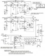
In order to do this at least reasonably quickly, I had to make some gross assumptions.
1) I didn't try to implement the output tubes' biasing scheme. I used 300 ohm cathode resistors bypassed with 470uF cathpde bypass capacitors to get 12.1V at the EL84 cathodes. I'm more interested in seeing what the driver stages are doing, so I figured I'd just get the output stage working.
2) I don't have the specs for a Dyna Z565 (primary L, primary DCR, secondary L, secondary DCR, leakage inductance) so I used a model of a Hammond 1605 that was handy. Again, I'm more interested to see what the driver stages are up to...
With the cathodyne's Rk lifted from ground and connected to the cathode of the input stage triode...
The open loop frequency response is -20dB down at 20kHz, referenced to 1kHz. That's a -10dB/octave rolloff.
Open loop frequency response at 1kHz is -1dB compared to 100Hz.
Open loop frequency response at 20Hz is -2.5dB compared to 100Hz.
Frequency response is slightly more dropped off at the frequency extremes with the cathodyne Rk connected to input triode cathode (i.e., with positive feedback).
I started with the driver stages set up as a standard cathodyne, with the cathodyne's cathode load resistor (Rk) grounded. Gain was about 49X (34dB).
Lifting the cathodyne Rk and connecting to the input triode cathode, gain rose to 169X (44.5dB). That's 10.5dB of positive feedback.
Adding the global NFB loop is problematic. High frequencies look very well compensated. I simulated out to 5MHz and see no high frequency resonoances. That's all good. However, I'm seeing a huge subsonic resonance, a spike at about 5Hz. I suspect the Hammond OPT has different leakage inductance and coil resistances than the Z565, so the problems I'm seeing may not be present in real life. I'm working on it...
...OK, I fixed that problem. Because this is an amplifier that uses a lot of global NFB, I wouldn't use tiny value coupling capacitors in the audio path (like the 22nF and 47nF caps you use in your design). I increased cap values to 470nF before the cathodyne and 1uF before the EL84 grids and the subsonic resonance came down a lot (but it's still there). This may still have more to do with the OPT than anything else, but... You don't want to force the global feedback loop to attempt to amplify low frequencies so much more than other frequencies because it 'sees' much lower amplitude low audio frequencies at the output than at the input. I'd also roll off some subsonic frequencies before they hit the input triode grid. A 470nF cap in series before the 100k volume control does the trick in simulation.
Amp gain after closing the global feedback loop fell to 16X (24dB). That means you have -20dB NFB from the global loop.
Leaving the gNFB closed but grounding the cathodyne Rk reduced gain to 13.6X (22.7dB, or a reduction of -2.5dB), which means the gNFB is dominating everything.
Closed loop and with the positive feedback from the cathodyne, frequency response looks commendably flat. It's flat down past 20Hz, about 0.5dB down at 20kHz.
I very much doubt this simulation can accurately portray THD, but for what it's worth, it predicts 0.037% THD with 1W out into 4 ohms (4 ohm tap on OPT secondary). 2nd harmonic dominates (-68dB), but there is appreciable 3rd harmonic present (-90dB).
Looks good to me!
Last edited:

For wiseoldtech's PP-UL EL84, here's the .asc. Just in case anyone else wants to play with it.
Attachments
Last edited:
I'll try. It will be tricky, since I don't know how you have the pot(s) adjusted. I'd have to 'build' it and experiment with settings.
Looks good to me!
Thanks Ron!
Square waves were if I remember, pretty tight, with minimal distortion.
The EFB as I remember puts a fixed 12.5 volts into those 5 ohm cathode resistors.
But that varies with the (minimal) PS sag, in order to follow control grid transients, preventing annoying overdrive distortion.
The Z565 overview on Triode Electronics site suggested "a healthy inductance over 1000."
I don't much get into all that, but they gave great reviews in a comparison shootout, which included the Hammond too, yet the Z565 topped the list.
That, and the EFB biasing on Gillespie's site showed substantial improvements in performance overall with a Dynaco 35 amp.
In 2003 when I purchased the Z565's they were a bit pricy, but I figured it's a One Time investment anyway.
Since then, OMG the prices slid up substantially. - see the triode site for that.
Nevertheless, if I'm going to the trouble of designing a tube amp, I want it to be satisfying, with no need to upgrade.
The bottom line is, this amp suits me just fine, and seems to hold its own against some very expen$ive commercial EL84 amps.
And having to drive a hungry pair of Advent floorstanding air-suspension 4 ohm'ers with grace and dignity, that's quite a challenge.
Last edited:
- Home
- Amplifiers
- Tubes / Valves
- Recommendations for PP EL84 circuits