PA0SU said:Cannot we get rid of this funny American bear? He bores me.
BTW, you have PCM7010? You collect DAT machines, too?
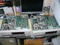
See how my friend and I toyed with Tascam DA-60 MK.II.
I have about 10 DATs, 7040, R500, 2700, 2500, two Tascams, one Fostex, etc.
Attachments
Re: Re: "Rutgers Osc"
 PASOU, finneybear, personal attacks and comments are strictly forbidden here. Stop it immediately and keep your comments directed toward technical discusssion or there will be a suspension of your posting privileges.
PASOU, finneybear, personal attacks and comments are strictly forbidden here. Stop it immediately and keep your comments directed toward technical discusssion or there will be a suspension of your posting privileges.Finney, Joseph K, and all
The PI loop is oscillating and not settling on a lock - it will drift into lock for a fraction of a second then out of lock drift again. So it is purely a matter of getting the PI loop and/or algorithm sorted. A similar setup has been built and tested by Joseph K and works as is. The common element is that we are both using a SM5842 DF and this will tolerate +/- 3/8 * LCRI error between BCKI and LCRI in jitter free mode and provides sufficient buffering of data for correct operation. As Joseph K points out with other DF other means of buffering are required.
cheers
Paul
if we were talkin bout multi-level 1bit or PWM dac then I'd understand the involvement of 2-20ps and even less jitter reaching the dac (PWM 20ps ~> 16bit PCM) . Suppose there are better things to make that happen besides ASRC , but personally I dont care. Once I can bypass digital filter then it becomes interesting.
spzzzzkt said:Finney, Joseph K, and all
The PI loop is oscillating and not settling on a lock - it will drift into lock for a fraction of a second then out of lock drift again. So it is purely a matter of getting the PI loop and/or algorithm sorted. A similar setup has been built and tested by Joseph K and works as is. The common element is that we are both using a SM5842 DF and this will tolerate +/- 3/8 * LCRI error between BCKI and LCRI in jitter free mode and provides sufficient buffering of data for correct operation. As Joseph K points out with other DF other means of buffering are required.
cheers
Paul
Paul,
As we have discussed, it all comes down to whether the FIFO in SM5842 is sufficient enough so the PI loop can take advantage of it. Yamaha has long been our customer and I had a long talk with a guy who did the DF. His answer is never to bet on the FIFO inside 5842. The FIFO is there for some other reason. Similarly, an ASRC chip has an even bigger buffer. Will it work? I will say not.
Again, the loop really depends on the clock recovered from the receiver chip. You may not get lucky all the time. How quickly will the PLL lock on has a big impact on the sound. Again, dont bet on the FIFO in the DF. A big enough standalone FIFO gives you a much more solid and generic solution. It will be more forgiving on the DPLL lock pattern. You can have a very fasting reacting PI loop, a small buffer, lock-on all the time yet the sound will be bad. The reason? The lock action itself become a source of jitter. This is why I said you need a cushion there.
tritosine said:if we were talkin bout multi-level 1bit or PWM dac then I'd understand the involvement of 2-20ps and even less jitter reaching the dac (PWM 20ps ~> 16bit PCM) . Suppose there are better things to make that happen besides ASRC , but personally I dont care. Once I can bypass digital filter then it becomes interesting.
Modern multibit delta sigma chips are actually less prone to jitter than classic 1bit DAC.
ASRC is good because it has a bigger input buffer yet there is still no guarantee that it's big enough.
Has DF or not is not the focus of the discussion here. It's about whether the buffer in a DF/ASRC can come to rescue and whether its size is adequate.
Sharing
Hi Herb,
How about going the extra mile and translating it into English? 😎
I think that this it what Spencer meant, with Nelsson Pass & sharing. I THINK he writes to us in Englich and not in Mandarin ??
Thanks & Greetings
Yours IJ
IJ
PA0SU said:
This means that you:
- cannot read
.
Hi Herb,
How about going the extra mile and translating it into English? 😎
I think that this it what Spencer meant, with Nelsson Pass & sharing. I THINK he writes to us in Englich and not in Mandarin ??
Thanks & Greetings
Yours
IJHerb,
Seems you forbidden me to learn Dutch from your website.
Niet Toegestaan
Je hebt geen toegang tot "/" op by-rutgers.nl.
Forbidden
You have no permission to access "/" on by-rutgers.nl.
Error
403
Seems you forbidden me to learn Dutch from your website.
Niet Toegestaan
Je hebt geen toegang tot "/" op by-rutgers.nl.
Forbidden
You have no permission to access "/" on by-rutgers.nl.
Error
403
Got some free time tonight, let me rephrase the whole thing again. Let's start with DIR901.
1. DIR9001 already has a controller-PLL-vcxo loop inside. TI/BB even gives it a fancy name:
Sampling Period Adaptive Controlled Tracking system (SpAct)
2. TI claims that this PLL loop will only add on 50ps jitter. I can see in reality it's more like
100ps. Still a very impressive number, consider there are so many components involved.
3. The PIC-ADC-VCXO loop is just like a second layer of PLL loop after DIR9001
4. With a tiny buffer, the PLL has to react quickly to lock on the incoming signal.
5. Yes, you can adjust the filter in the loop to lock on incoming signal aggressively.
The PLL will keep locking on beautifully but this also means the output clock signal will
follow the input clock closly.
6. This means you are actually following the input jitter instead of reducing the jitter.
7. VCXO in frequency transition is a phase noise generator. You also have to count in the extra
jitter generated by the components in the loop.
8. In short, this loop is not much different from the PLL loop inside DIR9001. This redundant
layer will just add more jitter to the signal.
9. To reduce jitter, you will have to create a circuit with high Q value, i.e. the output
clock and data should stay as stable as possible when the input keep changing.
A properly built buffer/FIFO control is one major solution.
Now go back to the ground zero:
1. If the SPDIF is clean, DIR9001 will do a job good enough. One extra loop with tiny buffer
most likely will just follow DIR9001's output and increase jitter
2. If the SPDIF is clean, DIR9001 + ASRC will be an attractive solution because ASRC has
a decent size buffer and the read out clock definitely has low jitter. Currently this is a very
popular option.
3. If the SPDIF is dirty, DIR9001 will struggle to follow the input, the second loop
will be busy with catching up all the input change, too.
4. CS8412/8414 has a relatively noisy PLL loop. In some scenarios, the second PLL with small
buffer may actually remove some jitter. Yet dont bet on this.
5. Therefore, it's much more beneficial to get a clean SPDIF output at the first place.
One can use Elso's I2SDirect scheme if you are willing to drill some holes. It completely omits the SPDIF interface. Shown is for NON-OS DAC.
No need for FIFOs, PLLs etc.
http://www.diyaudio.com/forums/showthread.php?postid=1355196#post1355196
No need for FIFOs, PLLs etc.
http://www.diyaudio.com/forums/showthread.php?postid=1355196#post1355196
Re: Sharing
Dear I......,
Do you know how much time this will take? The few English articles offer a lot for here, don't they?
irgendjemand said:
Hi Herb,
How about going the extra mile and translating it into English? 😎
I think that this it what Spencer meant, with Nelsson Pass & sharing. I THINK he writes to us in Englich and not in Mandarin ??
Thanks & Greetings
Yours
Dear I......,
Do you know how much time this will take? The few English articles offer a lot for here, don't they?
spencer said:Herb,
Seems you forbidden me to learn Dutch from your website.
Niet Toegestaan
Je hebt geen toegang tot "/" op by-rutgers.nl.
Forbidden
You have no permission to access "/" on by-rutgers.nl.
Error
403
I do not know what is going on. My povider says that there are too many Mb's downloaded within each day. If this is the consequence of my postings here..........
Finney,
Do You refer to me? If yes, then I will be forced to take this seriously, and act up consequently... These are false accusations in public. Show me only one link which points to me, selling something!!
George
This is funny that someone who has been selling things on diyaudio.com for years is accusing me that I am selling stuff here.
Are you getting nervous that someone is trying to promot something different from what you have selling here? Oh, yes, I remember that you have been selling this master clock solution with fiber optics thing!
Do You refer to me? If yes, then I will be forced to take this seriously, and act up consequently... These are false accusations in public. Show me only one link which points to me, selling something!!
George
Finney,
Technically, I might seem to be polemic, but in the reality I understand your point of view. As I told, without trying that pic - DAC - VCXO pll method, you can imagine problems with it, in advance - then those disappear, once you have done it in practice. Which I did.
Not true. Once got in lock, then EVEN WITHOUT a buffer, in practice, at this very moment, in my home, my pic pll solution can easily keep the two, slowly drifting clock domains so close to each other, that the otherwise very promptly muting PMD100 [again, without a buffer] will not mute more frequently, than 10- 20 secs.
With a tiny buffer, I don't get synchronization slips, ever.
Exactly this is why a PIC [that is, microcontroller] comes in handy. One can CHANGE the loop characteristics on the fly, lock fast, and once in lock, change to a very low corner frequency. At this moment I don't touch absolutely anything for 5-10-20 seconds, then adjust one step up or down, as needed.
And don't tell me that it's impossible, because exactly this is what happening in any ASRC; and this is what the SPACT patent is about! [changing loop parameters on the fly]
In the meantime, there is a DAC driving the VCXO, where one can have the parameters under control:
Can use a low noise reference.
Can keep impedances low [in analog PLL-s with a low corner frequency, the impedances must be high - means excess noise]
Can low pass filter the control DAC output extensively.
You mean the ~10msec settling time for a step in the control DAC, at every 10 -20 second? Ever listened to an LP? How much pops & cracks in 20 seconds?
With the difference, that here there is absolutely nothing noticeable, when the adjustment is happening. Again, I'm talking about facts, not fantasies.
Not much difference? An external VCXO with it's own low noise external power supply? A control scheme / control DAC with low noise, and anyway under free control of the developer? How is the DIR 's internal reference? I suppose it's a bandgap? How is the internal power supply in the DIR, locked up on the same chip with the noisy decoding engine? How is the corner freq for the DIR? I'm below 0.1Hz.
Exactly! This is what is happening in my house.
And a properly built PIC VCXO is another major solution, only much cheaper..
But then, it's up to the experimenter to decide, if such a solution would really help with the sound or not.
So let's hope Paul will arrive to a solution, and can decide it for himself..
Technically, I might seem to be polemic, but in the reality I understand your point of view. As I told, without trying that pic - DAC - VCXO pll method, you can imagine problems with it, in advance - then those disappear, once you have done it in practice. Which I did.
4. With a tiny buffer, the PLL has to react quickly to lock on the incoming signal.
Not true. Once got in lock, then EVEN WITHOUT a buffer, in practice, at this very moment, in my home, my pic pll solution can easily keep the two, slowly drifting clock domains so close to each other, that the otherwise very promptly muting PMD100 [again, without a buffer] will not mute more frequently, than 10- 20 secs.
With a tiny buffer, I don't get synchronization slips, ever.
5. Yes, you can adjust the filter in the loop to lock on incoming signal aggressively.
The PLL will keep locking on beautifully but this also means the output clock signal will follow the input clock closly.
6. This means you are actually following the input jitter instead of reducing the jitter.
Exactly this is why a PIC [that is, microcontroller] comes in handy. One can CHANGE the loop characteristics on the fly, lock fast, and once in lock, change to a very low corner frequency. At this moment I don't touch absolutely anything for 5-10-20 seconds, then adjust one step up or down, as needed.
And don't tell me that it's impossible, because exactly this is what happening in any ASRC; and this is what the SPACT patent is about! [changing loop parameters on the fly]
In the meantime, there is a DAC driving the VCXO, where one can have the parameters under control:
Can use a low noise reference.
Can keep impedances low [in analog PLL-s with a low corner frequency, the impedances must be high - means excess noise]
Can low pass filter the control DAC output extensively.
7. VCXO in frequency transition is a phase noise generator. You also have to count in the extra
jitter generated by the components in the loop.
You mean the ~10msec settling time for a step in the control DAC, at every 10 -20 second? Ever listened to an LP? How much pops & cracks in 20 seconds?
With the difference, that here there is absolutely nothing noticeable, when the adjustment is happening. Again, I'm talking about facts, not fantasies.
8. In short, this loop is not much different from the PLL loop inside DIR9001. This redundant layer will just add more jitter to the signal.
Not much difference? An external VCXO with it's own low noise external power supply? A control scheme / control DAC with low noise, and anyway under free control of the developer? How is the DIR 's internal reference? I suppose it's a bandgap? How is the internal power supply in the DIR, locked up on the same chip with the noisy decoding engine? How is the corner freq for the DIR? I'm below 0.1Hz.
9. To reduce jitter, you will have to create a circuit with high Q value, i.e. the output clock and data should stay as stable as possible when the input keep changing.
Exactly! This is what is happening in my house.
A properly built buffer/FIFO control is one major solution.
And a properly built PIC VCXO is another major solution, only much cheaper..
But then, it's up to the experimenter to decide, if such a solution would really help with the sound or not.
So let's hope Paul will arrive to a solution, and can decide it for himself..
The DIR9001 seems to work fine with the D1V3, its a great DAC but how could a Pic-VXCO have an audible affect on a analog stage that measures -65 dB 2nd harmonic THD? Wouldn't this overwhelm the approx. -110db vs -114 db jitter difference between a Pic-VXCO and the DIR9001 ?
Is there any analog stage where the difference between a Pic-VXCO and a DIR9001 is audible, I mean we are talking a hundred decibels below the music? I can barely hear 60 hz mains hum when it is -80 db down.
If I am wrong about this please explain.
Is there any analog stage where the difference between a Pic-VXCO and a DIR9001 is audible, I mean we are talking a hundred decibels below the music? I can barely hear 60 hz mains hum when it is -80 db down.
If I am wrong about this please explain.
regal said:
If I am wrong about this please explain.
Jitter on digital signals does NOT appear as noise in the audio!!! It influences the stereo image, de definition of it, etc. Up till now nobody knows why the human ear is so susceptible to jitter on the LATCH of a DAC.
- Status
- Not open for further replies.
- Home
- Source & Line
- Digital Line Level
- Real or fake PCM63?