Bernhard
Sie führen sich auf wie ein richtiger Deutscher: Wer nicht Ihre Meinung hat, wird geringschätzt.
Sie führen sich auf wie ein richtiger Deutscher: Wer nicht Ihre Meinung hat, wird geringschätzt.
Live is very easy in the internet, everybody can claim everything without having to proof it...
noise figures of my oscillator....
For a short time 'we' could borrow an 'FSUB Signal Source Analyzer' from R&S to calibrate my DC-receiver. These are the figures of the oscillator in my CD624 (on my web site)......
For a short time 'we' could borrow an 'FSUB Signal Source Analyzer' from R&S to calibrate my DC-receiver. These are the figures of the oscillator in my CD624 (on my web site)......
I'm confused that the figure did not come through.....
For a short time 'we' could borrow an 'FSUP Signal Source Analyzer' from R&S to calibrate my DC-receiver. These are the figures of the oscillator in my CD624 (on my web site)......
It seems to be impossible to attach a .pdf-file of 118 kb...
For a short time 'we' could borrow an 'FSUP Signal Source Analyzer' from R&S to calibrate my DC-receiver. These are the figures of the oscillator in my CD624 (on my web site)......
It seems to be impossible to attach a .pdf-file of 118 kb...
noise figures of my oscillator
Slow and steady wins the race......
For a short time 'we' could borrow an 'FSUP Signal Source Analyzer' from R&S to calibrate my DC-receiver. These are the figures of the oscillator in my CD624 (on my web site)......
Slow and steady wins the race......
For a short time 'we' could borrow an 'FSUP Signal Source Analyzer' from R&S to calibrate my DC-receiver. These are the figures of the oscillator in my CD624 (on my web site)......
Attachments
Re: Re: Jitter....
My experience is (quite) different
With certain speakers (e.g. Ensemble reference)I can hear the tiniest difference that occur when making changes the front end (source, amplifier).
With other speakers (e.g Totem Arro)I cannot hear any differences making the same changes to that same front end.
I demonstrated this to a number of people (friends, customers) visiting my lab
One needs a very transparent system to reveal differences. Mediocre application of chips will make them all sound the same, regardless of their type (opamp, DAC)
best
GuidoT
Bernhard said:
In a given environment the better DAC chip will always perform better, regardless of a little bit more or less jitter.
My experience is (quite) different
With certain speakers (e.g. Ensemble reference)I can hear the tiniest difference that occur when making changes the front end (source, amplifier).
With other speakers (e.g Totem Arro)I cannot hear any differences making the same changes to that same front end.
I demonstrated this to a number of people (friends, customers) visiting my lab
One needs a very transparent system to reveal differences. Mediocre application of chips will make them all sound the same, regardless of their type (opamp, DAC)
best
GuidoT
Re: Re: Re: Jitter....
That was about measurement of low level distortion only, not about the sound of a DAC.
Guido Tent said:
My experience is (quite) different
That was about measurement of low level distortion only, not about the sound of a DAC.
Dear PA0SU!
Thanks a lot for the drawing - it's a lot more than I would have expected!!
Given that also me had been using a scheme similar, the basics are not missing, and I just start to see the hints... Thanks! And will try and refrain from flooding You with questions.. 😀
Then, sincerely, I don't understand Bernhard's point about internet and claim's - I think it's enough a short look at your page to understand the thoughtfullness and the experience behind.
The real problem here is that Guido has overtaken us, and your experience will profit only to him, instead of fertilizing more public soils.. Hope that it will be a mutually fruitful collaboration, and wish good success!
Ciao, George
DC-receiver
George: crusial is the usage of an LT1028 just behind the DBM !!
Guido T: Hou maar op, daar is geen kruid tegen gewassen.🙄 🙄 🙄 😡 😡
George: crusial is the usage of an LT1028 just behind the DBM !!
Guido T: Hou maar op, daar is geen kruid tegen gewassen.🙄 🙄 🙄 😡 😡
Re: Re: Re: Re: Jitter....
OK, agreed
best
Guido
Bernhard said:
That was about measurement of low level distortion only, not about the sound of a DAC.
OK, agreed
best
Guido
Dear Herb,
Exactly this is why I was looking at your post-DBM amp, earlier on!
Thanks for the warning.
Then, pardon me, this is really the never ending story of questions forever..
I have always had this curiosity, about the circuit attached here - this would act on the lower spectra 1/f noise - why is it that nobody is using it in audio Xtal oscillators? There are some hidden drawbacks maybe?
Otherways, as regards your oscillator, -110db at 10Hz, very nice!
Ciao, George
George: crucial is the usage of an LT1028 just behind the DBM !!
Exactly this is why I was looking at your post-DBM amp, earlier on!
Thanks for the warning.
Then, pardon me, this is really the never ending story of questions forever..
I have always had this curiosity, about the circuit attached here - this would act on the lower spectra 1/f noise - why is it that nobody is using it in audio Xtal oscillators? There are some hidden drawbacks maybe?
Otherways, as regards your oscillator, -110db at 10Hz, very nice!
Ciao, George
Attachments
Re: Re: Re: Jitter....
Guido Tent,
Is it not obvious ?? 😉
Greetings,
IY.
Guido Tent said:One needs a very transparent system to reveal differences. Mediocre application of chips will make them all sound the same, regardless of their type (opamp, DAC)
Guido Tent,
Is it not obvious ?? 😉
Greetings,
IY.
Re: DC-receiver
Ich dachte, wir bleiben auf English hier... (I thought it is agreed here that we are corresponding in English....)
PA0SU said:Guido T: Hou maar op, daar is geen kruid tegen gewassen.🙄 🙄 🙄 😡 😡
Ich dachte, wir bleiben auf English hier... (I thought it is agreed here that we are corresponding in English....)
1/f noise
George,
The oscillator has been developped for radio-applications. Looking at my web site (wihout reading Dutch) you see most articles couver radio.
In Electron (the magazine of the Dutch radio ham society) there has been a polemic about oscillators for many many years. Then you are pointed to (all) the litterature on the subject.
I NEVER saw my circuit before. Why I have found it? Reading, discussing, expermenting is the way to new things. This very simple solution took me 15 (fiftien!) years......
It seems that 'audio' and 'radio' are different scenes: radio is science, audio seems to be a religion....
It is not only the 1/f-noise that will be suppressed. The agc works up till a 100 kHz you could find in my article.
Re: Re: Re: Re: Jitter....
not to everyone.....
GuidoT
irgendjemand said:
Guido Tent,
Is it not obvious ?? 😉
Greetings,
IY.
not to everyone.....
GuidoT
George: Figure 16. Bipolar oscillator schematic with emitter noise feedback (18)
Quote
I have always had this curiosity, about the circuit attached here - this would act on the lower spectra 1/f noise - why is it that nobody is using it in audio Xtal oscillators? There are some hidden drawbacks maybe?
Unquote
I missed the attachment of you for one reason or another.
My comments are:
- this oscillator runs on 1 GHz or about,
- the current in Q1 is at least 15 mA,
- the behaviour of oscillators on frequencies 100x higher than the frequencies we are talking about, is totally different,
- the circuit is for a dedicated frequency,
- the circuit is hardly reproducible.
For this reasons the diagramm is useless for our purposes.
I leave it to these comments...........
Dear Herb,
I know that the shown circuit, as a whole, was designed for HF, and as such, much more noisy than a 10MHz oscillator. I just wanted to point out the application of the emitter noise feedback technique, which is effective only in the low frequency range, and to quote the orig. article, "leads to a significant reduction of the low freq. noise to carrier modulation or flicker noise upconversion." They claim a simulated 40db, real ~20db reduction close to the carrier. [They show it from 100 Hz - 100KHz, but it works from DC]. In other words, [still from the article] this feedback acts on the nonlinearity of the active element, in a similar [?] way like your AGC kills one of the birds..
But I'm ready to accept the bashing, this is exactly why I was asking it from an expert like You, what is the possible drawback for it in an audio application...
Ciao, George
Ps.: As regards your circuit, I think I did not make it a secret that I find it really attractive, especially the clear and simple way as You deducted in the paper - it is to be tried, without doubts!
noise versus frequency
George,
remember that each doubling of the oscillator frequency theoretically produces 6 dB more sideband noise (if the 'quality' of the oscillators is similar) so, a 640 MHz oscillator noises 36 dB more than one at 10 MHz!
That's why I do not understand clock-freqencies (in SONY players) of 30 MHz and even higher....... Each devision by 2 lowers the noise again with 6 dB, IF THE ELECTRONICS ARE PERFECT........... but why so high? The target frequencies are equal in all CD players if the number of oversampling is equal.
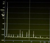
Hi folks,
here are my first measurements on my CD624 with a PCM63P....K. For pictures: see the home page of my web site.....
On my analyser a -60 dB signal has been displayed as -50 dB, so the noise flour is more than 120 dB down with an FFT size of 4096.
The 7th and 11th harmonics are more than 50 dB down the -60 dB signal of 991 Hz from a home made test disk.
Attachments
- Status
- Not open for further replies.
- Home
- Source & Line
- Digital Line Level
- Real or fake PCM63?