Hi Folks,
I just realized that I am down to my last 6 units of Gen2 RTR SSR's. These will sell out soon - is there any interest in GB#3 for these items? We will need interest for about 30 units (15 pairs) and I can get another batch started.
I just realized that I am down to my last 6 units of Gen2 RTR SSR's. These will sell out soon - is there any interest in GB#3 for these items? We will need interest for about 30 units (15 pairs) and I can get another batch started.
Hi X,
Did you connect the ground to the 0V terminal on the FH9 amp board. It is hard to see where the green ground wire from the "instant off module" ends up.
MM
Did you connect the ground to the 0V terminal on the FH9 amp board. It is hard to see where the green ground wire from the "instant off module" ends up.
MM
The reason I fear it is not easy is that it took me several tries to connect the compact PSU to the right ground location.
Hi X,
Since my 0V in the middle of the FH9 amp board is already occupied, can I use one of the 0V pads on either side of the FH9 amp board to connect the ground wire from the Instant Off board?.
MM
Since my 0V in the middle of the FH9 amp board is already occupied, can I use one of the 0V pads on either side of the FH9 amp board to connect the ground wire from the Instant Off board?.
MM
Hi X,
Since the instant off module wil power the SSR, I assume that the output from the instant off connects to the power input of the SSR, and the SSR molex output on the FH9 amp board is no longer needed/connected. Please correct me if I am wrong.
Regards,
Since the instant off module wil power the SSR, I assume that the output from the instant off connects to the power input of the SSR, and the SSR molex output on the FH9 amp board is no longer needed/connected. Please correct me if I am wrong.
Regards,
Hi X,
Since the instant off module wil power the SSR, I assume that the output from the instant off connects to the power input of the SSR, and the SSR molex output on the FH9 amp board is no longer needed/connected. Please correct me if I am wrong.
Regards,
Correct. You don’t need to use the SSR PSU output pin on the FH9HVX.
Hey X,
I ordered some of the SSR speaker protection boards v2.3, and when I placed my order I also ordered parts from mouser for the schematic in the lower right of the attached image assuming it was for the little black daughter boards. Now that I have the daughter boards in hand and getting ready to assemble them today, I am feeling confused.
My assumption is that I would populate the daughter boards with the parts from the attached schematic, and just leave out the parts not on the board? As in, no transistors and R3?
Attachments
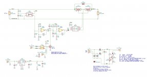
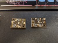
The boards you have are v2.3 and are a simple diode bridge and capacitor low capacitance PSU. The schematic you have is for the older version which has transistors for switching the logic. The v2.3 is simply a very small PSU that shuts down quickly. Here is a photo of the parts needed: 4 diodes, a cap, an LED and resistor. There is a schematic somewhere on this or the other thread. Much simpler as doesn’t require extra logic wires to the SSR.

Hi X,
Can one use a 22K ohm resistor in place of the 10K resistor when building the instant off modules. I have no 10K in my stock at present.
Thanks,
Myles
Can one use a 22K ohm resistor in place of the 10K resistor when building the instant off modules. I have no 10K in my stock at present.
Thanks,
Myles
That resistor is to drop the current for the LED indicator. You should size it depending on the voltage. Try to get about 2mA current so R=V/I. For example 24v/0.002mA=12k. So 10k would be close. But if 50v then 25k or 22k is close. If too small of a value LED will glow bright and fail early or blow out.
Thanks X, I left a reply in the FH9HVX thread as to what I had measured on the molex output from my instant off module (0V DC). I am going to rebuild the 2 modules, hence my post above.
So my transformer is an AN3436, dual secondaries are 36 V each. I tapped into both the blue/green secondary wire and brought those down to the Molex entry on the instant off board. After the diodes, the wires join to the positive side as shown in your self drawn image. After the halfway bridge, I should be about 24V DC, if you agree with my reasoning. So I see that I should be using a 10K value.
I do have 2 - 10K resistor's, they are 2 W variety that were spares from another project. I am not sure if they should/could / be used. Maybe best to wait until I can get some 10K resistors. Your thoughts?
Thanks,
MM
You may be missing a ground reference from the amp to the GND on the instant off board (you came up with that name). I called it the low capacitance PSU. Please draw a sketch of how it is currently wired. Hard to tell from your photos.
X,
Please see the pic below of how I wired the low capacitance PSU. Is my problem that the ground pin on X2 goes no where? Ground pin of X2 should be attached to the ground wire. Correct?

Please see the pic below of how I wired the low capacitance PSU. Is my problem that the ground pin on X2 goes no where? Ground pin of X2 should be attached to the ground wire. Correct?
- Home
- Group Buys
- Ready-to-Run (RTR) SSR DC Speaker Protection and Delay GB