There is another posting on this forum "How to build a 21st century protection board" that utilizes an arduino chip. It is complicated. Also, most amp boards would have some capacitance on the board itself and this won't cut that out.
If you use the posted “instant shutdown mod” trick to power the SSR, it will cut out in 100ms of power off and prevent turn off thump. Basically use a half bridge rectifier with two 1n400x diodes feeding a 22uF cap from the main power trafo secondaries. Take this small PSU and power the SSR power input jack with it. The moment the magnetic field collapses on the main power trafo, the 22uF cap decays in 100ms or so. Rather instantly and disengages the speakers from the amp. It works like a charm.
On the Gen2 RTR SSR, we provide an open collector logic control that could be connected to one’s own MCU to handle disconnect anyhow you like to program it.
On the Gen2 RTR SSR, we provide an open collector logic control that could be connected to one’s own MCU to handle disconnect anyhow you like to program it.
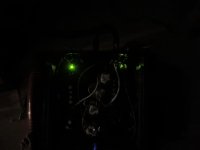
Its alive with bonus board!!
Planning to add RC delay later.
Planning to add RC delay later.
Attachments
Last edited:
Hi Fff0,
Nice! Your photo is of darkness and two LEDs which I presume are the SSRs? Do you have a lighted photo you can share?
Nice! Your photo is of darkness and two LEDs which I presume are the SSRs? Do you have a lighted photo you can share?
Ha, my work is messy and lousy thus didnt dare to take a brighter work. Added 88Mohm to form a RC delay with the 4.7uf.
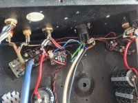
Tapped from existing supplies, luckily no ground loop heard on test speakers.
Initially, the bonus board output is wrongly connected but the 3 boards tolerated the error.
Somehow i believed it work as i accidentally short the speaker output and it turned off.
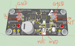
My humble suggestion for your consideration on next revision.
1. Square/ round pads, HI/ Low and pin 1/2 description together with A and K lettering are abit confusing for non engineer. + & - and or pictures will be better.
2. Speaker/ Amp I/O can be better spaced for lesser chance of short.
3. Revise post 1 to include build guide with pictures.
Tapped from existing supplies, luckily no ground loop heard on test speakers.
Initially, the bonus board output is wrongly connected but the 3 boards tolerated the error.
Somehow i believed it work as i accidentally short the speaker output and it turned off.
My humble suggestion for your consideration on next revision.
1. Square/ round pads, HI/ Low and pin 1/2 description together with A and K lettering are abit confusing for non engineer. + & - and or pictures will be better.
2. Speaker/ Amp I/O can be better spaced for lesser chance of short.
3. Revise post 1 to include build guide with pictures.
Attachments
Last edited:
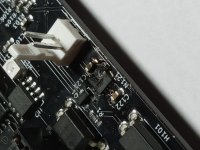
I’ll try to provide a better connection picture for the instant shutoff bonus circuit. Your solder joints could use a hotter iron. I feel like you may get some cold joints. Crimp Molex connectors were provided with the SSR. If you want to solder wires directly, remove the Molex KK header pins and solder to the board - not to the tips of the pins without insulation that’s asking for trouble. Also, you have a lot of exposed solder joints on what looks like high current or high voltage circuits. Be careful! Use crimp connectors for best reliability.
I have the bonus boards setup on the Xmas Amp and will go in and take some closeup photos of how this is hooked up:
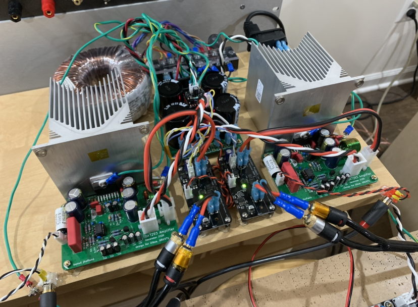
I have the bonus boards setup on the Xmas Amp and will go in and take some closeup photos of how this is hooked up:
Last edited:
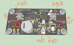
I would use the larger holes where the Fastons are soldered. The circled is for test leads but could work.
Is your amp a BTL (bridge tied load) amp where the -ve terminal is not 0vdc? The gen1 SSR does not have an isolated -ve speaker connection. On Gen2 it is isolated.
Is there a mechanical drawing for the PCB for drilling the chassis to mount it. I've done a couple of searches and can't see anything?
I’ll look for a drawing but I think the description in post 1 is sufficient for drilling:
PCB size is 70mm x 35mm and the M3 screw mounting holes are 62mm x ~26.5mm
PCB size is 70mm x 35mm and the M3 screw mounting holes are 62mm x ~26.5mm
I've just a quick check and my gen2 boards measure about 75mm x 35mm. I'll measure them accurately tomorrow as I only have a cheap plastic ruler to hand at the moment.
I think your are right - the size grew and I forgot to update the description. Both production Gen 1 and 2 are 75mm.
Sorry about that.
Sorry about that.
Correct X,
I just held up Gen2 against the Gen1 board and they are physically the exact same size, mounting holes lineup also 😉
I just held up Gen2 against the Gen1 board and they are physically the exact same size, mounting holes lineup also 😉
I think your are right - the size grew and I forgot to update the description. Both production Gen 1 and 2 are 75mm.
Sorry about that.
No problem X, stuff happens and it's really not a big issue, especially in the context of all you contribute here.
Expensive whoops!
Hi X,
In over 27 years of slinging solder, I just failed my first smoke test! Before & after this bit of excitement I checked and double checked all the wiring connections to the SSR boards so I'm at a bit of a loss to explain this. It was installed on the left channel of my fh9hvx.
I removed the board right after it went bang but I could hook it all up again if you want pics but here's a bit of info:
Neither boards LEDs lit up.
I was not yet using the remote boards as I hadn't populated them yet. They were powered from the amp boards' SSR 2 pin headers. The All C's psu tested near perfect at +/- 51v but I didn't check the voltage at the molex pins which might have been a bad decision but other than a catastrophic short somewhere, what could have caused this if the fault wasn't on the ssr board itself?
- Home
- Group Buys
- Ready-to-Run (RTR) SSR DC Speaker Protection and Delay GB