Hi legis31,
You have fried the on board 15V regulator. The only obvious thing that comes to mind that might have caused this is a reversal of the input power connections. The regulator itself is rated to 150V.
You have fried the on board 15V regulator. The only obvious thing that comes to mind that might have caused this is a reversal of the input power connections. The regulator itself is rated to 150V.
Hi Legis,
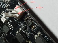
Sorry about your magic smoke session! 🙂 Did you have your power supply polarity hooked up as follows? This is the correct way.

It’s an easy fix - I can swap out a new voltage regulator for you. Send them back to me and I’ll take care of it, you just pay for shipping. If I can’t fix it, I’ll send you a replacement Gen2.
Cheers,
X
Sorry about your magic smoke session! 🙂 Did you have your power supply polarity hooked up as follows? This is the correct way.
It’s an easy fix - I can swap out a new voltage regulator for you. Send them back to me and I’ll take care of it, you just pay for shipping. If I can’t fix it, I’ll send you a replacement Gen2.
Cheers,
X
Attachments
Last edited:
X & Vunce,
The board was wired exactly the way you show in the pic.
After I've had some coffee I'll send a pic of the
amp board to verify that I don't have the ssr header installed backwards. The wiring harness is the same on both ends.
I also want to check the voltage polarity at the
at the output header on the amp.
Your offer to fix the ssr board is most generous! Thank you very much! Please PM me your shipping address & I'll get the board shipped out to you early this week.
Jim
Hi Legis,
Are these Gen2 SSR’s - I think so, because I notice the markings show a + next to the power input header.
That’s strange that neither of the LEDs lit up because I test each one for that fact before shipping them.
Can you take the one that did not blow up and apply something like 19v or 24v from a small power supply like a laptop brick? See if the LED works then.
Thanks,
X
SSR output voltage
Before I try what you suggested I have to ask this question. I checked the ssr output header by placing my dmm black lead on pin 1 & red on pin 2 & got -51vdc on both boards. Shouldn't it be + 51v?
Before I try what you suggested I have to ask this question. I checked the ssr output header by placing my dmm black lead on pin 1 & red on pin 2 & got -51vdc on both boards. Shouldn't it be + 51v?
SSR output voltage
It seems I fried the regulators on both SSR boards! There just wasn't any fireworks on the right board & I couldn't see the damage untill I removed it from under everything on the back panel. Dang!
It seems I fried the regulators on both SSR boards! There just wasn't any fireworks on the right board & I couldn't see the damage untill I removed it from under everything on the back panel. Dang!
Before I try what you suggested I have to ask this question. I checked the ssr output header by placing my dmm black lead on pin 1 & red on pin 2 & got -51vdc on both boards. Shouldn't it be + 51v?
There are two Molex KK output headers on the All Cee’s psu board,
X121 = +/G
X124 = -/G
You need to use X121 to power your SSR protection boards. You would get -51vdc if X124 was used.
Last edited:
Hi Legis,
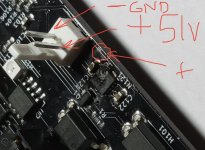
I am sorry, but there may be some confusion as to what is pin 1 and pin 2. And it depends on which way the tab is etc. please check your voltages according to the pin designation shown marked up in my photo. You can see a small +ve symbol on the silkscreen next to the side that is +ve.
So is your power cable from the PSU providing +ve 51v relative to the labeled +ve pin? That’s all that matters. Don’t go by pin 1 or 2.
It sounds like you had the polarity reversed - and I will need to put out a warning in the thread and on the shop listing saying this. It happens to all of us, and when in doubt always look at traces and see which is connected to the ground plane. No worries though, I’ll get you a replacement no charge.
Attachments
Last edited:
Powering the ssr boards
Vunce,
I had powered the ssr's from the amp boards & not the psu. If I use the + psu header do I have to hook up the ssr boards in series like X has suggested. When using the remote bonus board?
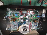
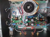
Gotta run some errands & I'll try and post a pic or two of the whole amp innards minus the now defunct ssr boards when I return.
Jim
Vunce,
I had powered the ssr's from the amp boards & not the psu. If I use the + psu header do I have to hook up the ssr boards in series like X has suggested. When using the remote bonus board?
Gotta run some errands & I'll try and post a pic or two of the whole amp innards minus the now defunct ssr boards when I return.
Jim
Yup, pics help lots 😉
I haven’t tried my Gen2’s yet, all my projects are loaded with Gen 1 SSR protection boards.
I haven’t tried my Gen2’s yet, all my projects are loaded with Gen 1 SSR protection boards.
Vunce,
I had powered the ssr's from the amp boards & not the psu. If I use the + psu header do I have to hook up the ssr boards in series like X has suggested. When using the remote bonus board?
Gotta run some errands & I'll try and post a pic or two of the whole amp innards minus the now defunct ssr boards when I return.
Jim
The power for the SSRs are not hooked up in series. Only applies to the logic control if you want to use the quick shutoff bonus board. It has open collector logic so that can be used to control two SSRs in series - that is the remote enable/disable jack. And you have to connect it in series with the logic output of the bonus board. The way open collector works is to think of it as a current sink (negative terminal). I think there is a diagram somewhere in this thread on how to connect it.
For the PSU if you are indeed powering from the Molex on the board, always use a voltmeter to check for polarity before connecting. And always go by what your visual inspection tells you. Not what is pin 1 or 2 which is up to the whims of whoever installed the jack with tab up or down. Unfortunately, I am a culprit of mounting the tabs to the “back” but proper notation usually has it mounted on the “front”. Little known trick is that the plastic Molex base with tab can be pulled off and flipped 180deg and it works that way too if you like your tabs one way vs another, after the fact. Just make sure your matching plug is consistent.
Very neat work on your amplifier chassis installation. Superb work! Sorry about the SSR blowing up on you.
Alternatively to using the bonus logic board, try making the low capacitance PSU for the SSRs. Take a secondary from the main power trafo and make a half wave bridge with two diodes, a 22uF cap and use that to power the SSRs. When you cut power, the SSRs shut down in 100ms and prevent turn off thump. This is described in here:
Ready-to-Run (RTR) SSR DC Speaker Protection and Delay GB
Last edited:
Header tab 180 switch
X,
Thanks for the tip on turning the tabs around!
I did just that so I can reuse the little harnesses
thus making the connection more or less idiot proof (for me anyway) when powering from the amp boards.
I don't recall a diagram for running the ssr boards in series when using a single
remote board but you did describe it in detail a while back.
Jim
The power for the SSRs are not hooked up in series. Only applies to the logic control if you want to use the quick shutoff bonus board. It has open collector logic so that can be used to control two SSRs in series - that is the remote enable/disable jack. And you have to connect it in series with the logic output of the bonus board. The way open collector works is to think of it as a current sink (negative terminal). I think there is a diagram somewhere in this thread on how to connect it.
Alternatively to using the bonus logic board, try making the low capacitance PSU for the SSRs. Take a secondary from the main power trafo and make a half wave bridge with two diodes, a 22uF cap and use that to power the SSRs. When you cut power, the SSRs shut down in 100ms and prevent turn off thump. This is described in here:
Ready-to-Run (RTR) SSR DC Speaker Protection and Delay GB
The Antek trans I used has dual 38v secondaries along with dual 15v secondaries despite the website saying it has one 18v pair & one 15v pair. Could one of the 15v pairs be used and would that be considered a separate ac source requiring the installation of D1 & D2 as per the ssr schematic notes? Or perhaps I should hace said using both 15v secondaries in series to constitute a center tapped secondary ?
Jim
Yes, you could use the 15v secondaries and that would be an excellent solution to keep the voltage down as to reduce dissipation in the votage regulator. Although I do not think 51v shoud blow it. It draws nominally 20mA x (51v-15v) =720mW dissipation. Warm, but not catastrophic blow up watm.
Yes - thanks for the note about Antek warning us not to use half wave bridges on a toroidal transformer. New to me. But it may have something to due with a DC offset saturation? The SSR only uses 20mA so probably not an significant effect on a 300VA transformer.
- Home
- Group Buys
- Ready-to-Run (RTR) SSR DC Speaker Protection and Delay GB